INSTALLATION & OPERATING INSTRUCTIONS 2 & 4-Stage Temperature Controllers For Raytherm™ & Hi Delta™ Boilers & Water Heaters Catalog No. 5000.66D Effective: 10-11-10 Replaces: 05-23-08 P/N 241177 Rev.
Rev. 5 is a completely new edition of this manual. Please discard any previous revisions.
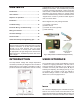
CONTENTS Sequence of Operation......................................4 of applications. They can also provide sequencing with lead/lag on two boilers. The Controllers may be used to provide a setpoint temperature, outdoor reset with reset override, or dedicated domestic hot water (DHW) generation and several options for external heater control. An additional relay contact is included with the “shipped loose” version to provide an alarm signal in case of a sensor failure. Installation .....................
DIP Switch Settings (DIP package located under cover on front of PCB) FACTORY (Default) SWITCHES Two-Stage (A) Heater Outlet Maximum: 200ºF (On) / 235ºF Heater (Off) (B) Heater Plant: Two Single-Stage (On) / One Two-Stage (Off) 235ºF Heater (Off) One Two-Stage (Off) Four-Stage (A) Heater Outlet Maximum: 200ºF (On) / 235ºF Heater (Off) (B) Heater Plant: Two Two-Stage (On) / One Four-Stage (Off) 235ºF Heater (Off) One Four-Stage (Off) B A Additional information can be gained by observing the Status fiel
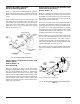
Primary/Secondary Piping Two Setpoints Operation, Primary Piping Mode 1 (MODE = 1) (Not Supported) In primary/secondary applications, the heater outlet temperature is typically higher than the system loop temperature. Therefore, the Controller uses an additional sensor (called the system sensor) to measure the temperature in the system. The operating sensor in primary / secondary piping applications is the system sensor. See Fig. 9. Mode 1 is designed for setpoint operation using Primary Piping.
Domestic Hot Water Operation, Uni-Temp 80 Piping (Mode 3) Outdoor Reset and Override Operation with Primary/Secondary Piping Mode 5 (Mode = 5) Mode 3 is designed for dedicated DHW operation using Unitemp 80 piping. The Controller operates the heater to maintain a tank temperature at the system sensor. Mode 5 is designed for outdoor reset and override operation using Primary /Secondary Piping. The CFH is available to provide outdoor reset for hydronic heating systems.
External Target Temperature Input and Override with Primary Piping Mode 6 (Mode = 6) (Not Supported) NOTE: To convert a 0-20 mA input signal to 0-10 VDC, a 500 Ω resistor must be added. See Fig. 13. Mode 6 is designed for a 0-10VDC or a 4-20 mA external input signal and override operation using Primary Piping. The external input signal creates an internal CFH and changes the heater target according to a linear scale. The control stages the heater to maintain the heater target at the heater outlet sensor.
Code Descriptions Heater Differential (DIFF) A heat source must be operated with a differential in order to prevent short cycling. The heater differential is divided around the heater target temperature. The first-stage contact will close when the water temperature at the operating sensor is 1/2 of the differential setting below the heater target temperature, and will open when the water temperature at the operating sensor is 1/2 of the differential setting above the heater target temperature.
Interstage Differential (STG DIFF) Proportional, Integral & Derivative (PID) The “interstage differential” is the temperature drop at which the next stage will turn on. Once a stage turns on, the next stage cannot turn on until the temperature drops the “interstage differential” below the temperature at which the previous stage turned on. The “interstage differential” is adjustable through the STG DIFF setting in the adjust menu.
Heater Target Temperature (BOIL TARGET) The heater target temperature is determined from the mode of operation and type of demand applied. The Controller displays the temperature that it is currently trying to maintain at the operating sensor as BOIL TARGET in the view menu. The operating sensor for modes 2, 3, 5 and 7 is the system sensor. If the Controller is not presently enabled for heat, it displays “- - -“ in the LCD. In Mode 8, no heater target temperature is generated.
Pump Exercising Internal DHW Demand If the system pump has not operated at least once every 70 hours, the control turns on the output for 10 seconds. This minimizes the possibility of the pump seizing during a long period of inactivity. A sensor is required to be installed in the tank and connected to the Com and the Sys/D terminals (6 and 4). A CFH for DHW is generated when the temperature at the DHW sensor drops 1/2 of the tank differential setting below the desired DHW tank temperature.
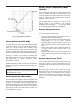
Reset Ratio Heater Design (BOIL DSGN) The controller uses the following four settings to calculate the Reset Ration (RR): The BOIL DSGN is the water temperature required to heat the zones when the outdoor air is as cold as the OUTDR DSGN temperature. RESET RATIO (RR) = BOILER DESIGN — BOILER START OUTDOOR START — OUTDOOR DESIGN Warm Weather Shut Down (WWSD) When the outdoor air temperature rises above the WWSD setting, the Controller turns on the WWSD segment in the display.
0-10 VDC 0-20 mA* Heater Target 0 0 - - - (OFF) 1 2 50ºF (10ºC) 2 4 68ºF (20ºC) 3 6 86ºF (30ºC) 4 8 103ºF (39ºC) 5 10 121ºF (49ºC) 6 12 139ºF (59ºC) 7 14 157ºF (69ºC) 8 16 174ºF (79ºC) 9 18 192ºF (89ºC) 10 20 210ºF (99ºC) A 4-20 mA signal can be converted to a 2-10 VDC signal by installing a 500 ohm resistor in parallel to the input signal on the controller’s terminals (terminals 9 & 10).
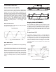
Fig. 20: Stage Actuation and Dead Bands BOILER OUTLET MAXIMUM TEMPERATURE CAUTION: The 120VAC connection must be applied to Terminal Block P3 (pins 1 and 2). Pin 3 must be connected to Ground. The external sequencer is able to operate the heater temperature. However, the BOIL OUT MAX setting limits the highest temperature at the heater outlet sensor. Should the heater outlet setting exceed the BOIL OUT MAX setting, the stage contacts are opened to shut off the heater.
Heater Contacts Heater Sys/D or DHW Sensor The Stg 1, Stg 2, Stg 3 and Stg 4 terminals (15 through 22) are isolated outputs in the Controller. There is no power available on these terminals from the Controller. These terminals are to be used as a switch to either make or break the heater circuit. When the Controller requires heater stages to fire, it closes the contact between the appropriate terminals. Either a System Sensor or DHW Sensor may be connected to the Controller.
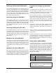
5. After 13 seconds, Stage 4 is turned on. 6. After 16 seconds, the pump and stages 1 to 4 are shut off. The alarm contacts are closed for 10 seconds. 7. The control exits the test sequence and resumes normal operation. Sensor Resistance Fig. 21: Multi-meter NOTE: Make sure ALL power to the devices and wiring harness is off. Connecting the Controller Apply power to the Controller.
ELECTRICAL WIRING / TROUBLESHOOTING Pin # Label 1 CD Function 24 VAC return power. Pin # Label Function 13 Pmp Pump Contact – Not to exceed 5 amps. No power output. 14 Pmp Pump Contact – Not to exceed 5 amps. No power output. Dem 1 Enable/Disable - Hot 24 VAC Incoming power for the Controller. Bring hot 24 VAC from the heater transformer. 15 Stg 1 Stage 1, Odd-numbered pin on the stage connection plug 3 Dem 2 Indirect DHW Override – Hot 24 VAC – Incoming power for the demand.
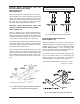
WIRING CONNECTIONS Factory-Mounted On Hi Delta heaters, the multi-stage Temp Tracker can be ordered factory-mounted. The controller is already powerd by the heater, the inlet and outlet sensors are installed in the inlet/outlet header, and the controller alarm is connected to the UDB diagnostic board. The heater stage connections are also wired. TO UDB P4 Fig.
CONTROLLER SETTINGS Field Installation Field wiring must be connected to the terminal block on the back side of the controller mounting bracket. Follow the wiring diagram as specified in Fig. 25 below. Tables F through T describe the “View” and “Adjust” menus. They also show the default settings as well as any possible adjustment ranges. 120V Fig.
VIEW MENU MODE 2 (With Default Settings Shown) The View menu items display current operating temperatures and system status information. Use the Item button (see Fig. 5) to view items in this menu. Item Field Range Description ---, 35 to 266°F (2 to 130°C), OFF BOILER TARGET The boiler target is the temperature the control is currently trying to maintain at the boiler supply sensor or the boiler outlet sensor.
ADJUST MENU MODE 2 (Page 1 of 2) (With Default Settings Shown) The Adjust menu items are the programmable settings used to operate the system. Press and hold all three buttons for one second to enter the Adjust menu, then select the desired item using the Item button. Finally, use the ▲ or ▼ button to make the adjustment (see Fig. 6). Item Field Range Description 1 to 8 MODE Select the operating mode for the control.
ADJUST MENU MODE 2 (Page 2 of 2) Item Field (With Default Settings Shown) Range Description Au, 0:30 to 9:55 min STAGE DELAY Select the minimum time delay between stages. Note: This setting is only available when STAGE MODE is set to PId. Au, 2 to 42°F (1 to 23°C) DIFFERENTIAL Select the boiler differential. Note: The automatic setting is only available when STAGE MODE is set to PId staging.
VIEW MENU MODE 3 (With Default Settings Shown) The View menu items display current operating temperatures and system status information. Use the Item button (see Fig. 5) to view items in this menu. Item Field Range Description ---, 35 to 266°F (2 to 130°C), OFF TANK TARGET The temperature that the control is trying to maintain in the tank. -20 to 266°F BOILER OUTLET Current boiler outlet water temperature as measured by the boiler outlet sensor.
ADJUST MENU MODE 3 (Page 1 of 2) (With Default Settings Shown) The Adjust menu items are the programmable settings used to operate the system. Press and hold all three buttons for one second to enter the Adjust menu, then select the desired item using the Item button. Finally, use the ▲ or ▼ button to make the adjustment (see Fig. 6). Item Field Range Description 1 to 8 MODE Select the operating mode for the control.
ADJUST MENU MODE 3 (Page 2 of 2) Item Field (With Default Settings Shown) Range Description Au, 0:30 to 9:55 min STAGE DELAY Select the minimum time delay between stages. Note: This setting is only available when STAGE MODE is set to PId. OFF, 0:20 to 9:55 min, On °F or °C 2 to 42°F (1 to 23°C) 0:10 to 8:00 min PUMP DELAY Select the system pump purge time after shutting off the burner. TEMPERATURE UNITS Select to display temperature in degrees Fahrenheit or in degrees Celsius.
VIEW MENU MODE 5 (With Default Settings Shown) The View menu items display current operating temperatures and system status information. Use the Item button (see Fig. 5) to view items in this menu. Item Field Range Description -60 to 190°F (-51 to 88°C) OUTDOOR Current outdoor air temperature as measured by the outdoor sensor.
ADJUST MENU MODE 5 (Page 1 of 3) (With Default Settings Shown) The Adjust menu items are the programmable settings used to operate the system. Press and hold all three buttons for one second to enter the Adjust menu, then select the desired item using the Item button. Finally, use the ▲ or ▼ button to make the adjustment (see Fig. 6). Item Field Range Description 1 to 8 MODE Select the operating mode for the control.
ADJUST MENU MODE 5 (Page 2 of 3) Item Field (With Default Settings Shown) Range Description 120 to 230°F (49 to 110°C), OFF BOILER MAXIMUM Select the maximum boiler target temperature. OFF, 80 to 180°F (27 to 82°C) BOILER MINIMUM Select the minimum boiler target temperature. 0:00 to 3:00 min (1 second increments) FIRE DELAY Select the amount of time required for combustion pre-purging, ignition and the flame to be established. Note: This setting is only available when STAGE MODE is set to Pld.
ADJUST MENU MODE 5 (Page 3 of 3) Item Field (With Default Settings Shown) Range 0:10 to 5:00 min Description MINIMUM ON TIME Select the minimum amount of time that the stage contact must remain on before it is allowed to turn off. Note: This setting is only available when STAGE MODE is set to P. 0:10 to 5:00 min MINIMUM OFF TIME Select the minimum amount of time that the stage contact must remain off before it is allowed to turn back on.
VIEW MENU MODE 7 (With Default Settings Shown) The View menu items display current operating temperatures and system status information. Use the Item button (see Fig. 5) to view items in this menu. Item Field Range Description ---, 35 to 266°F (2 to 130°C), OFF BOILER TARGET The boiler target is the temperature the control is currently trying to maintain at the boiler supply sensor or the boiler outlet sensor.
ADJUST MENU MODE 7 (Page 1 of 2) (With Default Settings Shown) The Adjust menu items are the programmable settings used to operate the system. Press and hold all three buttons for one second to enter the Adjust menu, then select the desired item using the Item button. Finally, use the ▲ or ▼ button to make the adjustment (see Fig. 6). Item Field Range Description 1 to 8 MODE Select the operating mode for the control.
ADJUST MENU MODE 7 (Page 2 of 2) Item Field (With Default Settings Shown) Range 0 to 10°F (0 to 6°C) 0:10 to 8:00 min Description STAGE DIFFERENTIAL Select the interstage temperature differential between stages for proportional staging. Note: This setting is only available when STAGE MODE is set to P. INTERSTAGE ON DELAY Select the amount of time that must pass once a stage has been turned on in order to allow the next stage to turn on. Note: This setting is only available when STAGE MODE is set to P.
VIEW MENU MODE 8 (With Default Settings Shown) The View menu items display current operating temperatures and system status information. Use the Item button (see Fig. 5) to view items in this menu. Item Field Range -20 to 266°F (-29 to 130°C) -20 to 266°F (-29 to 130°C) 0 to 252°F (0 to 140°C) 0 to 999 Description BOILER OUTLET Current boiler outlet water temperature as measured by the boiler outlet sensor. BOILER INLET Current boiler inlet water temperature as measured by the boiler inlet sensor.
ERROR MESSAGES ALL MODES E01 The control was unable to read a piece of information from its EEPROM memory. The control will stop operation until all settings in the Adjust menu have been checked by the user or installer. To clear the error message, set Access Level DIP Switch A to Factory (on position), then check all Adjust menu items. BOILER OUTLET SENSOR SHORT CIRCUIT The control is no longer able to read the boiler outlet sensor due to a short circuit.
TECHNICAL DATA (Controller only) qUICK START SET-UP & PROGRAMMING TIPS 4-Stage Controller – PN 601880 2-Stage Controller – PN 601881 1. Determine piping arrangement and mode number as depicted on pages 5 through 7.
www.raypak.com Raypak, Inc., 2151 Eastman Avenue, Oxnard, CA 93030 (805) 278-5300 Fax (805) 278-9725 Litho in U.S.A.