
Quick Start Guide
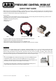

PRESSURE CONTROL MODULE
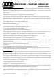
Part Number: 0830001
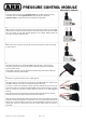
2.
Install the pressure sensor into a regulated output port (outward pointing arrows)
of the PRV. Any of the PRV regulated output ports may be used, select the
regulated output port that best suits your installation configuration.
3.
Attach the two connectors of the wiring harness to the two solenoid coils of the PRV.
Note that the connector with the purple wire should be matched only with the deflate
valve coil (shown on the right directly opposite to the exhaust fitting). Retain the
connectors using the supplied screws.
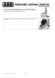
4.
Attach the sensor connector of the wiring harness to the pressure sensor by inserting
it until it clicks in.
5.
Route the wiring harness to the desired PCM mounting location, and plug in the
connector until it clicks. Secure the wiring with cable ties making sure not to leave
the wires under tension.
Fix the PCM in position using the screw tabs provided. Fixing with double sided tape
or cable ties would also be acceptable.
6.
Connect the ring terminal (black wire) to a body ground.
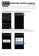
7.
The PCM red wire is intended to be connected to the ARB compressor switch so that
the PCM is powered only when the compressor switch is turned on.
To do this, remove the compressor harness red wire terminal from the rear of the
compressor switch, and connect the PCM piggyback quick connect terminal in its place.
Then re connect the compressor harness red wire terminal to the PCM piggyback
terminal.
Alternatively, it can be connected to the pressure switch terminal with the red wire.
Protect this 12V wire with split conduit and secure with cable ties.
Note: the red wire provides 12V power to the PCM. Connect it to a 12VDC circuit that is
powered on when the compressor is switched on. The circuit must also be off when the
vehicle key is in the off position, hence not a permanent battery connection or else the
module will continue to draw power from the vehicle battery when the vehicle is
turned off.
Latest Revision Date: 09/06/2020 Page 2 of 7