
Installation Guide


7
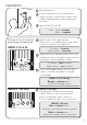
Trouble Shooting
Ensure all tests are undertaken by a qualified, trained engineer.
Ensure safe working practices are followed at all times.
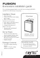
Step 1: Basics
• CheckpolarityofLampconnection
red=+ve, black=-ve
• Ensurepoweris12-24VDC/24VAC
• Checkphotocellisworking-coverphotocell,lightshouldturnon.
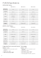
• Ensurepowersupplyissuitablyratedtoproduct-checkpage6for
specifications
If OK…
Step 2: Lamp Test
• Checkcurrentdrawoflampcorrespondstospecicationonpage6
• Checkcurrentoflamp–seeinstructionsforcorrectcurrentsetting
To check lamp current remove +ve (red) lead from power supply and connect
multimeter (set to 10A) in line with the lamp. [One lead of multimeter in common
(COM), other lead into 10A socket of multimeter; set multimeter to read Amps].
Refer to PSU Specifications for correct current settings, see page 6.
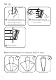
Step 3: Set-up Camera, lens and illumination
• Checkalignmentoflamp
• Checkcameralens–fullyopenatnight&setcorrectly
• CheckmodelnumbertoRaytecperformancespecicationtoensurerequired
distance is achievable
Step 4: Call Raytec for further assistance
Note down:
•Modelandserialnumberofilluminator
•Cameramakeandmodel
•Lensmakeandmodel
If the Raytec lamp is still not delivering the required performance, please contact
us for further assistance.