
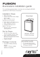
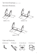
Installation Guide


Specifications subject to change without notice. Installation
to be carried out by suitable trained and qualified personnel.
!
Install in a well
ventilated area
Do not continually
stare at lamp
2
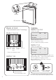
LED illuminator
Bracket
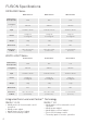
RM/RL F 25 & 50
PhotocellPower
adjust
Photocell
adjust
12/24V
AC/DC
input
Power
in
Made in UK
P-cell
adjust
-
+
Power
adjust
-
+
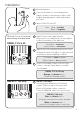
RM/RL F 100
Telemetry Input &
Photocell following contact
Power
adjust
-
+
Power
in
Made in UK
P-cell
adjust
-
+
Telemetry
P/C Contact
Back of Unit
‘Command and Control’ Technology™
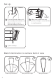
DC AC
Black wire - ~
Red wire + ~
DC AC
Black wire - ~
Red wire + ~
RM/RL F 25 & 50
Cables
1x four core cable
Orange and Brown wires=
Photocell following contact.
Volt free output. Non polarity sensitive.
+ Photocell following contact
RM/RL F 100
1x four core cable loom
RM/RL 100 is supplied with additional cable loom
Black & White wires = Photocell following contact.
Volt free output. Non polarity sensitive.
Brown & Blue wires = Telemetry connection.
Requires volt free input.
1. 5m