
Installation Guide
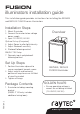


Installation
3
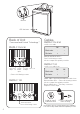
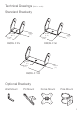
Mount illuminator
Connect Illuminator to low voltage power
supply: Installers can extend or reduce lead
length using appropriate cable and weather
proof box
Input 12-24V DC/ 24V AC
2
3
1
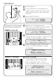
RM/RL F 100 only:
Telemetry input and photocell following
contact. Remove cap on telemetry and
photocell following contact connector.
Connect additional cable loom (see below).
5
7
6
4
1
2
Adjust Photocell sensitivity. Remove the cover
and turn the ‘photocell adjust’ to alter photocell
sensitivity to ambient lighting condition.
Photocell following contact, volt free relay
contact - normally open (day) to normally
closed (night).
Clockwise = more sensitive
Anticlockwise = less sensitive
RM/RL F 25 & 50 only
Orange and brown wires =
Photocell following contact
RM/RL F 100 only
Blue and black wires =
telemetry connection for remote operation
White and brown wires =
photocell following contact connection
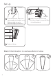
Adjust Power to alter light intensity.
Remove the cover and turn the ‘power adjust’
to alter the intensity of the light level.
Clockwise = increase
Anticlockwise = decrease
Note: Red = positive
Black = negative
Power
in
Made in UK
P-cell
adjust
-
+
Power
adjust
-
+
Power
adjust
-
+
Power
in
Made in UK
P-cell
adjust
-
+
Telemetry
P/C Contact
Optional Set-up (if required)
Note: Factory set to max. power
RM/RL F 25 & 50
RM/RL F 100 only