Quick Start Safety Information: White Light and IR Variants (850nm & 940nm) Caution – Risk Group 2. Avoid Exposure / use protection. See Safety Information in FULL Instruction Guide for details.
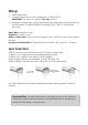
Wiring: 1. 2. Mount Illuminator Connect Illuminator to low voltage input 12-24V AC/DC IMPORTANT: For Vario 16 variants : 24V only AC/DC 3.
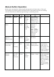
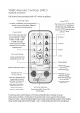
Manual Button Operation Buttons are accessed by removing the base plate at the bottom of the unit. The number of button pushes indicated below are based on the user starting with the illuminator in either programming or operating mode.
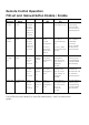
Action Required Disable / Enable Manual Buttons Step1 : LHS Button 1 x Long Push (4s), then 2 x short Push LHS Step 2 : LED RHS Button Flashing Push to Amber cycle Disable / Enable RHS LED Disable – Red Enable - Green Full Re-set (including PIN re-set) Keep both buttons depressed during power up – LEDs will both flash Amber Flashing Amber then solid green after button release Flashing Amber then Flashing Amber after button release Keep both buttons depressed during power up – LEDs will both flash Am
Press again for 4 seconds to disable manual buttons – must be done within 5 minutes of remote disable This will NOT remove PIN if present
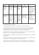
Remote Control Operation PIN set and Manual Button Disable / Enable Action Required Available Mode Step1 Step 2 LHS LED RHS LED Comment Disable Remote Programming Mode Press button on VRC for 4 seconds N/A Solid Green Flashing Amber to Solid Amber to Off Illuminator will go to Operating Mode. RHS LED turns Off when in Operating Mode.
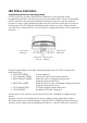
LED Status Indicators: Programming Mode and Operating Mode On first power up (Factory Default) the illuminator automatically enters Programming Mode. It will then time out automatically after 7 Days to Operating Mode unless the user actively disables the remote control or uses the manual buttons in which case Operating Mode will start 30 minutes after the last manual button press. The LED Indicators feedback the mode you are in.
RESET: Settings Re-set : Pressing and holding the RESET BUTTON on the remote control or using the manual buttons to complete a RESET will restore the factory settings to the illuminator. Note : It will not remove a PIN if one is present. Full Re-set : Re-cycling the power whilst pressing both manual buttons will restore factory settings and remove a PIN if one is present. Both indicator LEDs flash amber for both above re-sets when complete.
Full Installation Guide Contents : Ver.
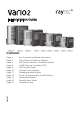
Box Contents : VARIO2 Illuminator , spare 60° beam angles ILS (ILS: Interchangeable Lens System) Accessories (Optional) :VARIO Remote Control for additional Programming; 80˚ beam and 120˚ beam angle ILS; Bracketry VARIO2 Enhancements • Increased Distance • Default time for illuminator to go into Operating Mode reduced • PIN function for enhanced security • Manual Control added – Push Buttons Accessible on the illuminator • Improved RESET Options • The 3 single colour feedback LED’s have been replaced with 2
Installation Steps: 1. VARIO2 is factory set and delivered with a 35˚ beam width. To alter to 10˚, simply remove interchangeable lens (ILS). See page 4 for detailed instructions To alter to 60˚, replace with other ILS lens supplied. 2. Mount Illuminator 3. Connect Illuminator to low voltage input 12-24V AC/DC (For Vario 16 variants : 24V AC or DC only) 4-6.
Factory Default Set-Up: 35˚ Beam Angle ; Max 100% Power Telemetry Input – closed ; Photocell sensitivity – MID Status LEDs – ON ; No PIN Set ; Manual Button Control Enabled Programming function will auto-disable after 7 Days VARIO2 Complete Set up and Installation Step 1. Select different beam angle – if required VARIO is factory set and delivered with a 35˚ beam width angle. To alter to 10˚, simply remove interchangeable lens (ILS). To alter to 60˚, replace with other ILS lens supplied.
Step 2. Mounting Illuminator VARIO2 is delivered as standard with bracket at the bottom of the unit. This can be moved to the top of the unit if required. See page 18 for optional brackets Step 4. Telemetry Input (Orange & Purple) As default the telemetry input will be wired together so that the unit turns on/off automatically via the photocell. If required to be activated by PIR or alarm system, connect to appropriate, volt-free or TTL input.
Step 5. Photocell following output (White & Yellow) Volt free output - normally open (day) to normally closed (night). Connect direct to camera if required to control switchover of day/night cameras. Step 6. Programme using optional VARIO Remote Control (VRC) or the manual control buttons. Step 7. Set PIN (If Required) (Can only be done with the optional VARIO Remote Control(VRC) LED Status Indicators- Feedback system : There are two tri-coloured LEDs visible on the base of the VARIO2 illuminator.
Programming Mode and Operating Mode On powering up the illuminator, it automatically enters programming mode to allow the user to adjust set-up and operation. The programming mode automatically times out after 7 Days or until the user actively disables the remote control or the unit times out 30 minutes after any press of the manual buttons on the illuminator.
VARIO Remote Controller (VRC) : Optional Accessory Full instructions provided with VRC when supplied Press again for 4 seconds to disable manual buttons – must be done within 5 minutes of remote disable Note : Reset button will not remove a PIN if one is present Note : Unless detailed as part of the functionality, if an invalid or blocked command is attempted, both LEDs will flash RED 8
Extra VRC Functionality : - PIN Function For extra security VARIO2 allows a PIN (Personal Identification Number) to be set for each lamp The PIN is set by using the Vario Remote Control (VRC). There are five buttons / characters on the remote that can be used for this purpose.
PIN Function Detail : The PIN is set by using the Vario Remote Control (VRC). There are five buttons / characters on the remote that can be used for this purpose. They are Power 5, Power 1, Min Photocell (Smallest moon), Max Timer (Full Red Circle) & Timer Disable ( Timer Circle image with a line through) . Note – invalid characters will not be recognised. To create a PIN, press STATUS BUTTON for 4 seconds. LHS LED will flash RED/GREEN. This indication will always show that you are in PIN mode.
To delete an existing PIN you first need to be in Programming Mode by entering your PIN. Once in Programming Mode, press STATUS BUTTON for 4 seconds to go into PIN set mode. LHS LED will flash RED / GREEN and RHS LED FLASHING RED. Instead of entering one of the known legal characters press the RESET BUTTON four times. The illuminator will return to programming mode.
Manual Control – Buttons : The two manual control buttons gives a wide selection of user control : 1. Power Control – 100%, 80%, 60%, 40%, 20% of maximum. (Factory Default is 100%) 2. Photocell Control – 3 levels, 25 Lux on, 50 Lux off, 10 Lux on 30 Lux off, 5 Lux on 15 Lux off and photocell disable. 3. Turn LED indicators on & off 4. Illuminator Reset Options 5. Disable Remote Control and enter Operating Mode or Enable Remote Control and enter Programming Mode 6.
Manual buttons can be accessed by removing the base cover of the illuminator The buttons are active in both programming mode and operating mode regardless of whether a PIN is present or not unless you have previously disabled the manual buttons As soon as manual button mode is entered by pressing the Left Hand Button, the standard LED indicators will be disabled and will indicate a new set of information, Standard LED indicators are enabled after exiting manual button modes.
Manual Setting / Level Indication using RHS Button : The RHS BUTTON will only have an effect if you have selected a mode using LHS Button – pressing RHS Button without previously pressing LHS Button will have no effect on the Illuminator operation – it is used to control the setting for the mode chosen by LHS Button When you select a mode using LHS BUTTON, the LHS LED will confirm which mode you are in and RHS LED will show the current setting / level of that mode for the Illuminator.
Illuminator Settings Mode Detail : Enter this mode by a momentary press of LHS button to turn LHS LED solid RED. Pressing the LHS button again will turn the LED solid GREEN and pressing a third time will turn the LED solid AMBER. Each of these colours indicates which setting mode you are in.
Illuminator Security Modes Detail : Enter this mode by a long 4 second press of LHS button to turn LHS LED Flashing RED. Pressing the LHS button again momentarily will turn the LHS LED Flashing GREEN and pressing a third time momentarily will turn the LHS LED Flashing AMBER. Each of these colours indicates which setting mode you are in.
NOTE – If no buttons are pressed within 2 minutes the illuminator times out and returns to the previous mode it was in – either Programming Mode or Operating Mode. Disabling the Manual Buttons : If the Illuminator is in Operating Mode, once the disable manual buttons command is executed the buttons will be disabled after 30 minutes. This is to allow the user to re-enable manual buttons if required.
Power Up Functionality : After power is supplied to the unit : If no PIN is present the Illuminator will go into Programming Mode for 7 Days and then will default to Operating Mode - During this time if the remote is used to change settings the illuminator will still default into Operating Mode after 7 Days from the power up (unless the remote disable button is used to change the illuminator to Operating Mode) - During this time if the manual buttons are used in either Illuminator Settings Modes or Illumina
Standard Bracketry : Supplied with the Product (Model Dependant) (not to scale, dimensions rounded to nearest mm) Optional Bracketry (not to scale - other Bracketry also available) VUB-Pole VUB-Wall VUB-Plate VUB-PSU Plate Wall Mount 19 PTZ Mount Dome Mount Pole Mount
VARIO2 Specifications Table : Infra-Red Series & White-Light Series i16 w16 i8 w8 i6 i4 w4 i2 w2 10° 500m (1640ft) 250m (820ft) 350m (1148ft) 180m (591ft) 200m (656ft) 144m (472ft) 110m (361ft) 78m (256ft) 60m (197ft) 35° 250m (820ft) 125m (410ft) 165m (541ft) 95m (312ft) 120m (394ft) 78m (256ft) 65m (213ft) 54m (177ft) 40m (131ft) 60° 135m (443ft) 70m (230ft) 95m (311ft) 50m (164ft) 70m (230ft) 54m (177ft) 35m (115ft) 36m (118ft) 25m (82ft) 80° 105m (344ft) 48m (157
VARIO2 Troubleshoot : Ensure all tests are undertaken by a qualified, trained engineer. Ensure safe working practices are followed at all times. Step 1: Basics • Check polarity of illuminator connection red=+ve, black=-ve • Ensure power is 12-24V AC or DC (For Vario 16 variants : 24V AC or DC only) • Ensure telemetry wires are shorted out or valid telemetry input (zero volt or TTL) is applied and correctly wired • Check photocell is working.
Step 3: Set up camera, lens, and illumination • Check model number to Raytec performance specification to ensure required distance is achievable; - Check unit is set to max power Check orientation of unit and ensure it is pointing in correct direction Check angle of unit (Interchangeable lens) – Too narrow may cause hot spots and the aperture of the camera lens to close down. Too wide and there may be insufficient light on scene and light going where it is not needed.
- In extreme sunlight conditions, distance between remote and unit may need to be reduced Programming may be disabled. Enter PIN to retrieve control or RESET illuminator using one of the two RESET modes. Battery failure. Check battery on remote (CR2025). Test 3 volt battery, replace if necessary. Ensure battery has clean contacts. Remote failure.
Raytec Global (excluding Americas) Tel: +44 (0) 1670 520055 Fax: +44 (0) 1670 819760 sales@rayteccctv.com Americas Tel: +1 613 270 9990 Toll Free: +1 888 505 8335 ussales@rayteccctv.com www.rayteccctv.com 24 Ver.