
OPERATOR'S MANUAL Digital Thermometer 3i


Raynger 3i Series Operator’s Manual A-1
APPENDIX A: OPTICAL
HOW TO READ THE OPTICAL CHARTS
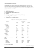
The optical charts indicate the nominal target spot diameter at various distances from
the sensing head. Information on the top line of each chart shows the different spot
diameters at the distances from the sensor given on the bottom line (see Figure A-1).
All measurements are in millimeters or meters and inches.
Model
Type
Focus Point D:S = Distance to spot divided by spot diameter at the focus point
Far Field D:S = Ratio at distances greater than 10x the focus distance
How to calculate spot sizes
To calculate a spot size between two
known points on an optical chart, use
the following formula:
S
x
= S
n
+ x (S
f
- S
n
)
S
x
= Unknown spot size
S
n
= Smaller known spot size
S
f
= Larger known spot size
D
x
= Distance to unknown spot
D
n
= Distance to smaller known spot
D
f
= Distance to larger known spot
(D
x
- D
n
)
(D
f
- D
n
)
Target spot size
at focus point
Diameter of target
spot size in inches
Distance from sensor
to object in inches or feet
Distance from sensor to
object in millimeters or meters
Diameter of target
spot size in millimeters
Spot Diameter (in)Spot Diameter (mm)
LTCL2
LTCL3
5000
300015001000
36
60
120
180
0
0
0.9
1.9
4.6
7.3
23
48
118
DISTANCE: SENSOR TO OBJECT IN MILLIMETERS
DISTANCE: SENSOR TO OBJECT IN INCHES
FOCUS POINT D:S = 75:1 FAR FIELD D:S = 20:1
0.3 in @ 24 in
8 mm @ 610 mm
Focus Point
IR Spot Diameter at Lens = 23 mm (0.9 in)
Laser Diameter at Lens = 40 mm (1.6 in)
IR Beam Profile
Laser Profile
203
Figure A-1: How to Read the Optical Charts