
User's Manual
P25net Channel Controller Operations Manual
1-3
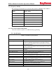
1.3.5 Frequency Stability
The following recommendations are from the P25 standard (ANSI/TIA-102.CAAB-C):
Assigned Frequency
(MHz)
Frequency Stability Parts per
Million (PPM)
Below 100 2.5
138-174 1.5
406-512 0.5
764-806 0.1
806-869 0.15
896-941 0.1
1.3.6 Narrowband Channel Bandwidth
The radio should be capable of 12.5kHz channel programming.
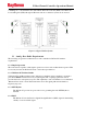
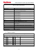
1.4 Specifications
Table 1-1 P25net CC Specifications
Power
AC Power Input 90-264VAC, 47-63Hz, 20VA from external AC adapters (supplied) for
connection to DC Inputs A and B (J1and J2 on rear panel). J1/J2 are
5.5mm x 2.5mm locking DC Power Jacks (Switchcraft L712A; mating
plug Switchcraft 761K).
DC Power Inputs A and B +11.0-13.2VDC 1A for connection to J1and J2 on rear panel; J1/J2 are
5.5mm x 2.5mm locking DC Power Jacks (Switchcraft L712A; mating
plug Switchcraft 761K).
Dual Power Source DC inputs A and B allow connection of 2 power sources for added
reliability.
Signal Inputs
Receive Baseband Audio Pin 7 on the D15F rear panel connector Channels 1-4;
0-3000Hz, 3vpp (1.06 vrms) maximum
RSSI Pin 8on the D15F rear panel connector Channels 1-4;
Receive Strength Signal Indicator (RSSI) signal from radio; 0-5VDC.
Signal Outputs
Transmit Baseband Signal Pin 6 on the D15F rear panel connector Channel 1-4
0-3000Hz, 3vpp (1.06vrms) maximum
PTT or Keyline Pin 5 on the D15F rear panel connector Channel 1-4
Open Collector, active low
Analog Ground Pins 14,15 on the D15F rear panel connector Channel 1-4
Ground reference for the input/output signals
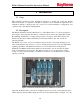
Data Connections
IP Connection RJ45 connectors on the front and rear panel.