INSTALLATION & OPERATING INSTRUCTIONS Raytherm™ Heating Boilers Models 133–4001 Type H WARNING: Improper installation, adjustment, alteration, service or maintenance can cause property damage, personal injury or loss of life. Refer to this manual. Installation and service must be performed by a qualified installer, service agency or the gas supplier.
Rev. 35 reflects the following: Changes to: Certifications on page 6, Flow chart on page 34 Additions: Canadian Installation Code references on pages 6, 8 and 24, adjustment procedure for two-stage Robertshaw gas valve (including Fig. 47) on pages 31-32.
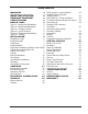
CONTENTS WARNINGS 4 Pay Attention to These Terms 4 MODEL IDENTIFICATION 5 RECEIVING EQUIPMENT 6 CERTIFICATIONS 6 BOILER TYPES 6 Type H1 - Mechanical Modulating 6 Type H2 - Motorized Modulating 6 Type H3 - 2-Stage Controls 6 Type H4 - On-Off Controls 6 Type H5 - Mechanical Modulating 6 Type H9 - 4-Stage 6 INSTALLATION 6 Installation Codes 6 Installation Base 7 Clearances 7 Outdoor Boilers 8 High-Wind Conditions (Outdoor Units Only)8 Combustion and Ventilation Air (Indoor Units Only) 8 Venting 9 Indoor Instal
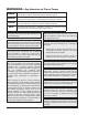
WARNINGS—Pay Attention to These Terms DANGER: Indicates the presence of immediate hazards which will cause severe personal injury, death or substantial property damage if ignored. WARNING: Indicates the presence of hazards or unsafe practices which could cause severe personal injury, death or substantial property damage if ignored. CAUTION: Indicates the presence of hazards or unsafe practices which could cause minor personal injury or product or property damage if ignored.
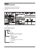
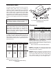
MODEL IDENTIFICATION The model number of a boiler can be found on the Sales Order and the boiler's rating plate. The example below identifies what the characters of the model number represent.
RECEIVING EQUIPMENT BOILER TYPES Type H1 - Mechanical Modulating, Models 133-1826 On receipt of the equipment, visually check for external damage to the carton or the shipping crate. If either is damaged, make a note on the Bill of Lading and report the damage to the Carrier immediately. Remove the boiler from the carton or the shipping crate. Central heating boiler with 150°-210°F mechanical modulating gas valve(s). The number of valves varies with the model size. On occasion, items are shipped loose.
Installation Base The boiler should be mounted on a level, non-combustible surface. Boiler must not be installed on carpeting. The boiler can be installed on a combustible surface only when a suitable floor shield base is provided. Raypak offers an optional floor shield base which can be factory installed on all indoor models except Model 133; the Model 133 floor shield base is shipped loose and must be installed by the contractor. Do NOT use the shipping crate base as an installation base.
Outdoor Boilers NOTE: The boiler shall be installed in a space large in comparison to the size of the boiler. Large space is defined as having a volume at least sixteen (16) times the total volume of the boiler. These boilers are design certified for outdoor installation. Boilers must not be installed under an overhang within three (3) feet from the top on the boiler. Three (3) sides must be open in the area under the overhang.
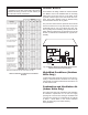
Venting CAUTION: Combustion air must not be contaminated by corrosive chemical fumes which can damage the boiler and void the warranty. Outdoor Installations Model 133 a. All Air From Inside The Building: Each opening shall have a minimum net free square inches as noted in Table E. Model Sq. Inches Model Sq.
1. 2. 3. 4. Remove jacket top panel. Remove and discard inner stack adapter panel. Install jacket top panel. Insert tabs of outdoor top into keyholes located on jacket top panel (4 places). See Detail A. 5. Snap tabs on outdoor top into the locked position of the keyhole so the top will not pull out. See Detail B. JACKET TOP FASTENING SCREW Fig. 8: Installing Outdoor Top Detail—Models 514–824 Models 926-1758 Boilers are shipped with outdoor vent terminal factory installed.
Fig. 9: Indoor Installation—Model 133 Models 181-401 & 182-400 4. Turn the stack (drafthood) upside down and set it down bottom side up. Indoor Stack Installation 5. Turn the jacket top panel (removed in step 1) upside down and place it over the stack. 1. Remove the louvered jacket top by removing four (4) #10 flathead screws. 6. Attach the three (3) mounting brackets to the stack using the screws provided and the holes that are pre-drilled in the stack.
7. Turn the assembled stack and jacket top, rightside up. The jacket top will be trapped between the brackets and the top of the stack. Place the stack over the inner stack adapter panel flanged hole and lower the louvered jacket top panel back into its original position. Reinstall the four (4) #10 flathead screws removed in step 1 above. Fig. 11: Boiler Before Drafthood Installation—Models 181-401 & 182-400 Fig. 10: Indoor Installation—Models 181-401 & 182-400 Models 181-401 & 182-400 1.
Vent Piping WARNING: Indoor boilers require a drafthood that must be connected to a vent pipe and properly vented to the outside. Failure to follow this procedure can cause fire or fatal carbon monoxide poisoning. Vent piping the same size or larger than the drafthood outlet is recommended, however, when the total vent height is at least 10 ft.
Type "B" double-wall or equivalent vent pipe is recommended. However, single-wall metal vent pipe may be used as specified in the latest edition of the National Fuel Gas Code ANSI Z223.1. 10' OR LESS VENT CAP 2' MIN 2' MIN Manifolds that connect more than one boiler to a common chimney must be sized to handle the combined load. Consult available guides for proper sizing of the manifold and the chimney. At no time should the area be less than the area of the largest outlet.
Vent Damper Installation On vertical vents, the vent damper may be mounted with the actuator in any position. On horizontal vents, do not mount the actuator either directly above or directly below the vent pipe; mount the vent damper actuator to the side of the vent. (Models 133 Through 261) Where Required Location The vent damper is set up for a continuous pilot system.
EFFIKAL® RVGP CAUTION: Install the vent damper to service only the single appliance for which it is intended. if improperly installed, a hazardous condition, such as an explosion or carbon monoxide poisoning, could result. Vent Damper Normal Operation Summary For safe, efficient operation, the vent damper and all flue product carrying areas of the appliance must be checked annually, with particular attention given to deterioration from corrosion or other sources. Check vent damper operation as follows: 1.
*Low NOx units not available for propane. Table G: Maximum Equivalent Pipe Length Venting of Diaphragm Gas Components CAUTION: The boiler and its manual shut-off valve must be disconnected from the gas supply during any pressure testing of that system at test pressures in excess of 1/2 PSIG. Dissipate test pressure in the gas supply line before reconnecting the boiler and its manual shut-off valve to gas supply line. FAILURE TO FOLLOW THIS PROCEDURE MAY DAMAGE THE GAS VALVE.
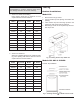
MAXIMUM AND MINIMUM FLOW RATES 2-PASS HEAT EXCANGER MODEL SIZE 133* 182/181 260/261 330/331 400/401 514 624 724 824 926 962 1083 1125 1178 1223 1287 1336 1414 1468 1571 1631 1758 1826 2100 2500 3001 3500 4001 GPM 22 MAX T 10 P FT 14.7 GPM 10 MI N T 22 45 45 45 45 90 90 90 90 90 90 90 90 90 90 90 90 90 90 90 90 90 90 200 200 200 200 200 7 10 12 15 9 12 13 15 17 18 20 21 22 22 24 24 26 27 29 30 32 34 17 21 25 29 33 9.2 9.4 9.6 9.8 9 9.5 10 10.5 11 11 12 12 12.5 12.5 13.2 13.2 14 14 14.5 14.5 15.4 15.
CONTROLLER SENSOR (LESS THAN 4-STAGE) 5’ MAX 5’ MAX CONTROLLER SENSOR (4-STAGE OR MODULATION) Note: Expansion tanks (supplied by others) should be installed per manufacturer's instructions. Fig.
MAXIMUM OF 12”OR 4 PIPE DIAMETERS 5’ MAX CONTROLLER SENSOR Reverse return piping is a proper method of manifolding multiple boiler hook-ups to ensure balanced flow through each boiler. Valves on supply and return are needed to isolate any boiler, as required. Fig.
CONTROLS Operating Controls Economaster Controls Modes H1 and H5 - Mechanical Modulation Models 133-1826 with mechanical modulating controls have one or more Robertshaw (Invensys) Unitrol 7000 Series hydraulic snap-on thermostatic combination gas valves. These dual-seat combination valves have the pressure regulator and 24 volt operator built-in. The hydraulic actuator will throttle the boiler input to adjust the firing rate and meet the required load.
Mode H3 - 2-Stage Firing MODULATING VALVES W/ BUILT-IN REGULATOR The boiler will fire at low fire when there is closure across the stage 1 contacts. Thereafter, it will fire at high fire when there is closure across the stage 2 contacts. Numerous staged controllers are available. Mode H4 - On/Off Firing The boiler will fire at full fire when there is closure across the TH contacts. Numerous mechanical staged controllers are available (see Fig.
Flow Switch This dual purpose control shuts off the boiler in the case of a pump failure or low water condition. It is mounted and wired in series to the main gas valve. Standard on all models except the 133. NOTE: Flow switch will not operate if flow is less than 12 gpm. Fig. 31: 2-Stage Tankstat Limit Controls Manual-Reset High Limit All models except 133 are equipped with a manual reset high limit. Set the manual limit to its maximum set point. Fig.
ELECTRICAL CONNECTIONS Low Water Cut-Off (Optional) The probe-type low water cut-off automatically shuts down burner whenever water level drops below the probe for more than 2 seconds. A 30-second time delay prevents premature lockout due to temporary conditions such as power failure or air pockets. CAUTION: Label all wires prior to disconnection when servicing controls. Wiring errors can cause improper and dangerous operation. Verify proper operation after servicing.
T & P GAUGE (NOT SHOWN) MECHANICAL MODULATING GAS VALVES WITH REGULATOR INLET HI-LIMIT Fig. 37: General Location of Controls START-UP Ethylene Glycol Systems Heating Boilers Before Start-Up Fill through filler opening on the top on the Air-X Tank to solution desired. Always maintain solution level in sight glass.
START-UP LIGHTING INSTRUCTIONS FOR BOILERS WITH STANDING PILOT. For Models 133, 182, 260, 330 & 400 FOR YOUR SAFETY READ BEFORE LIGHTING WARNING: If you do not follow these instructions exactly, a fire or explosion may result causing property damage, personal injury or loss of life. • A. This appliance has a pilot which must be lighted by hand. When lighting the pilot, follow these instructions exactly. B. BEFORE LIGHTING smell all around the appliance area for gas.
LIGHTING INSTRUCTIONS FOR BOILERS WITH ELECTRONIC IGNITION (IID) For Models with Manual Gas Valves FOR YOUR SAFETY READ BEFORE OPERATING WARNING: If you do not follow these instructions exactly, a fire or explosion may result causing property damage, personal injury or loss of life. A. This appliance is equipped with an ignition device which automatically lights the pilot. Do not try to light the pilot by hand. B. BEFORE OPERATING smell all around the appliance area for gas.
For Models with Automatic Gas Valves soap and water solution. Bubbles indicate a gas leak. 2. Adjust pilot to obtain a normal flame enveloping 3/8 to 1/2 inch [9.5 to 12.5 mm] of the thermocouple or generator tip. Lighting Instructions 1. Close all gas valves. Turn off electrical power supply. Wait five (5) minutes. 3. Place system in operation, and: a. Check for satisfactory ignition of main burner. b.
at once. Pilot burner should ignite after gas reaches the pilot burner. b. Spark ignition should cut-off when pilot flame is established. c. Main gas valve should open and main burner should ignite after gas reaches the burner port. Inspections Burners Clean main burners and air louvers of dust, lint and debris. Keep boiler area clear and free from combustibles and flammable liquids. Do not obstruct the flow of combustion and ventilation air. Make visual check of burner and pilot flame.
Operation Replace any parts showing wear. c. Check pump coupler for wear and vibration. On call for heat, the ignition system, consisting of an electronic spark module, and gas pilot system is energized. Providing pilot is proven, blower will start running, the main gas valve will open and the boiler will operate. When the operating control is satisfied the boiler will shut down. 7. Check flow switch paddle. 8. Clean room air intake openings to ensure adequate flow of combustion and ventilation air.
size, and connections which comply with all applicable codes. 1. 2. 3. 4. 5. Flame Roll-Out Safety Switch The boiler is equipped with a cut-off device to prevent flame roll-out in the event the heat exchanger becomes blocked. This is a "manual reset" type rollout switch, that must be reset by a service technician after any over temperature conditions have been fixed. Excessive restriction in the heat exchanger flue passage may cause the switch to disable the boiler. 6. 7. 8. 9. 10. 11.
7. Using an Allen wrench, turn the screw clockwise to increase or counterclockwise to decrease high fire manifold pressure –see Fig. 47. 8. Install the spring, weight and aluminum cap –tighten the cap using same # of turns as was used in removing the cap. 9. For low fire adjustment, tighten the aluminum cap to increase and loosen to decrease low fire manifold pressure. 10. Install 2-stage solenoid valve and turn heater on, check manifold pressures. 11.
TROUBLESHOOTING WARNING—HIGH VOLTAGE: For qualified technicians ONLY. Electrical—Electronic Ignition IID NOTE: Some heaters may be equipped with an ignition module that shuts off pilot gas if pilot fails to light. To reset, interrupt power to heater. Intermittent Pilot System Honeywell S8600 START TURN GAS SUPPLY OFF.
Electrical—Standing Pilot WARNING—HIGH VOLTAGE: For qualified technicians ONLY. For Service Technicians START BOILER IF PILOT BURNER LIGHTS BUT MAIN BURNERS DO NOT IF PILOT BURNER DOES NOT LIGHT CHECK FOR 24 V AT GAS VALVE CHECK THERMOCOUPLE IF NO 24 V IF 24 V: CHECK TRANSFORMER OUPUT FOR 24 V IF NO 24V: REPLACE TRANSFORMER IF O.K.
TYPICAL ON-OFF INTERMITTENT IGNITION CONTROL WIRING DIAGRAM 35
MECHANICAL PROBLEM POSSIBLE CAUSE CORRECTIVE ACTION When boiler is turned on nothing happens. Pilot is not lit……………………………… No power to the boiler…………………... Light pilot. (Standing pilot models) Check the circuit breaker, outdoor controller, etc., upstream of boiler. If power to Leads L1 and L2 of transformer, but no power on 24V side, replace. Jumper thermostat. Replace with new if boiler fires. If power to toggle switch, but not through switch, replace. If power to relay, but not operating, replace.
Pumps Pump Loses Prime Failure To Pump 1. Air leaks in suction line. 1. Pump not properly primed. 2. Excessive amount of air in water. 2. Wrong direction of rotation. 3. Water seal in stuffing box not functioning. 3. Speed too low. 4. Excessive suction lift and pump operating too near shut-off point. 4. Total head too high. Overloaded Driving Unit Reduced Capacity And/Or Head 1. Air pockets or leaks in suction line. 1. Head much lower than that for which pump is designed. 2. Clogged impeller.
RAYPAK TUBE CLEANING KIT Extension Pieces (5) Auger with Carbide Tip P/N 052871F - 5/8 DIA. Wire Brush P/N 052870F - 7/8 DIA. Fig. 51: Raypak Tube Cleaning Kit Service Burner Tray Removal Repair Section 1. Shut-off power and gas supply to the boiler. Disconnect union(s) and pilot tubing, then loosen and remove burner hold-down screws. Tube Cleaning Procedure 2. Disconnect wires at gas valve and slide burner tray out.
NOTE: If the heat exchanger is sooted badly, the burner hold-down bracket and spacer can become distorted from direct flame impingement and this usually necessitates replacement of these parts. 2. Lift burners from slotted spacer and slide from orifices. Clean with a wire brush. 3. Clean orifice(s) as necessary. Pilot Removal and Cleaning Remove front inspection panel. 3. Remove wires to high limit and loosen screws holding high limit to cabinet. 4.
5. Remove heat exchanger corner brackets. 10. If gas piping was disconnected, reconnect gas piping system and check for leakage using a soapy solution. 6. Remove combustion chamber clips at the four corners of the heat exchanger. 11. Check for correct water pressure and water level in the system. Make sure that system pump operates immediately on the call for heat. The system is ready for operation. 7. Lift heat exchanger straight up using caution not to damage refractory. 12.
5. Insert replacement tube by inserting the end with the most fins removed in the opening of one tube sheet. Slide tube until the opposite end clears the other tube sheet and fit the tube into the hole. NOTE: In extreme cases it may be necessary to remove the heat exchanger completely for cleaning. The simplest method is steam cleaning at a local car wash. DO NOT WIRE BRUSH! 6. Insert the tube roller into tube opening up to stop, making certain that 1/8" of tube projects beyond the tube sheet.
Catalog Number: 1900.10H Effective 08/01/10 LIMITED WARRANTY RAYTHERM - TYPES H AND WH Models: 133 - 4001 SCOPE Raypak, Inc. (Raypak) warrants to the original owner that all parts of this heater which are actually manufactured by Raypak will be free from defects in materials and workmanship under normal use and service for the specified warranty periods and subject to the conditions set forth in this Limited Warranty.
www.raypak.com Raypak, Inc., 2151 Eastman Avenue, Oxnard, CA 93030 (805) 278-5300 Fax (805) 278-5468 Litho in U.S.A.