INSTALLATION & OPERATING INSTRUCTIONS Raytherm™ Hot Water Supply Heaters Models 0133–4001 Type WH L W ® LLC WARNING: Improper installation, adjustment, alteration, service or maintenance can cause property damage, personal injury or loss of life. Refer to this manual. Installation and service must be performed by a qualified installer, service agency or the gas supplier.
Rev.
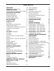
CONTENTS WARNINGS 4 Pay Attention to These Terms 4 GENERAL SAFETY 5 Time/Temperature Relationships in Scalds 6 RECEIVING EQUIPMENT 6 Model Identification 6 General Specifications 7 All Models (Approved) 7 Hot Water Supply Heaters 7 INSTALLATION 7 Installation Codes 7 Installation Base 7 Clearances 8 Specifications and Dimensions 9 Outdoor Water Heaters 12 Combustion Air (Indoor Units Only) Air for Combustion and Ventilation 12 Venting 13 Vent Piping 17 Vent Damper Installation 18 Plumbing 20 Flow Rates 22 P
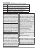
WARNINGS—Pay Attention to These Terms DANGER: Indicates the presence of immediate hazards which will cause severe personal injury, death or substantial property damage if ignored. WARNING: Indicates the presence of hazards or unsafe practices which could cause severe personal injury, death or substantial property damage if ignored. CAUTION: Indicates the presence of hazards or unsafe practices which could cause minor personal injury or product or property damage if ignored.
WARNING - CALIFORNIA PROPOSITION 65: This product contains chemicals known to the State of California to cause cancer, birth defects or other reproductive harm. ! DANGER Vapors from flammable liquids will explode and catch fire causing death or severe burns. Do not use or store flammable products such as gasoline solvents or adhesives in the same room or area near the water heater. Keep flammable products: 1. Far away from heater, 2. In approved containers, 3. Tightly closed and 4.
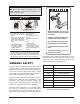
RECEIVING EQUIPMENT Time/Temperature Relationships in Scalds WARNING: Pump motors should NOT be supported by any type of stand or support from above due to possible misalignment of pump and motor which might occur. The temperature of the water in the storage tank heater can be regulated by setting the temperature dial on front of the tankstat. To comply with safety regulations, the tankstat was set at its lowest setting before shipment from the factory.
General Specifications TYPE WH3 with 2-STAGE CONTROLS Models 0181-4001 The Raypak water heaters are design certified and tested under the latest requirements of the American National Standard, ANSI Z21.10.3/CSA 4.3. Each heater has been constructed and pressure tested in accordance with the requirements of Section IV of the American Society of Mechanical Engineers Code, and factory fire tested. Materials are CSA-certified for lowlead content (<.25%).
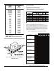
Clearances Heater Floor Base Model Part Number Number 001749 0133 058313 0182/0181 0260/0261 058314 0330/0331 058315 0400/0401 058316 0514 056199 0624 056200 0724 056201 0824 056202 0926* 054597 1083* 054598 1178* 054599 1287* 054600 1414* 054601 1571* 058378 1758* 058379 0962 059233 1125 059234 1223 059235 1336 059236 1468 059237 1631 059238 1826 059239 *Models with factory installed floor shield as standard. BOLD TYPE indicates Low NOx models.
NOTE: The heater shall be installed in a space large in comparison to the size of the heater. Large space is defined as having a volume at least sixteen (16) times the total volume of the heater. Specifications and Dimensions MODEL 0133 Indoor Outdoor Model Number Input MBH Recovery GPH* Recovery GPH* WH-0133 136.0 135 132 NOTE: Ratings are shown for elevations up to 2,000 feet. For elevations over 2,000 feet, reduce ratings 4% for each 1,000 feet above sea level.
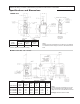
MODELS 0514-0824 Indoor/Outdoor Model Number WH-0514 WH-0624 WH-0724 WH-0824 Input MBH 511.5 627.0 726.0 825.0 Dimensions (in inches) Recovery GPH* 508 623 722 820 Width Gas Conn. A G K L 32-3/4 37-1/2 41-5/8 45-3/4 1 1 1 1 10 12 12 14 25-3/8 29-1/2 34-1/4 38-1/2 Flue Diameter NOTE: Ratings are shown for elevations up to 2,000 feet. For elevations over 2,000 feet, reduce ratings 4% for each 1,000 feet above sea level. * Recovery based on manufacturer’s rating.
MODELS 0 926-1758 Dimensions (in inches) Model Number Input MBH Recovery GPH* Width Gas Conn. Water Conns. A G H WH-0926 926.0 920 52-3/8 1 2-1/2 WH-1083 1083.0 1076 59-1/4 1 2-1/2 WH-1178 1178.0 1171 63-5/8 1-1/4 2-1/2 WH-1287 1287.0 1279 68-5/8 1-1/4 2-1/2 WH-1414 1413.0 1404 74-7/8 1-1/4 2-1/2 WH-1571 1570.0 1560 82-1/8 1-1/4 2-1/2 WH-1758 1758.0 1747 89-3/8 1-1/4 2-1/2 NOTE: Ratings are shown for elevations up to 2,000 feet.
Outdoor Water Heaters CAUTION: Combustion air must not be contaminated by corrosive chemical fumes which can damage the heater. Measures must be taken to prevent the entry of corrosive chemical fumes to the combustion and ventilation air supply. Such chemicals include, but are not limited to, chlorinated and/or fluorinated hydrocarbons such as found in refrigerants, aerosol propellants, dry-cleaning fluids, degreasers, and paint removers.
Models 0181-0401 and 0182-0400 NOTE: If louvers, grills or screens are used on the openings, obtain the net free area from their supplier or manufacturer. If the design free area of a louver is not known nor available, it shall be assumed that wood louvers will have 20-25 percent free area and metal louvers will have 60-75 percent free area as specified in the National Fuel Gas Code. Outdoor Top Venting Outdoor Installations Model 0133 1. Remove the front (4) screws. 2.
Models 0514-0824 Models 0926-1758 1. Lower outdoor "Stackless" top onto unit. Position top so it is centered on unit from side-to-side and front-to-rear. Heaters are shipped with outdoor vent terminal factory installed. Models 2100-4001 These units are not certified for outdoor installation. Indoor Installations Model 0133 Refer to Fig. 9 on the following page. 1. Shut-off main electrical power switch to heater. 2. Turn heater manual ON/OFF switch, located in upper control panel, to the "OFF" position.
Fig.
Models 0181-0401 and 0182-0400 Models 0514-0824 Vent Terminal/Indoor Stack Installation Locate and assemble as shown below. Secure with screws supplied in envelope in carton. 1. Remove the louvered jacket top by removing four (4) #10 flathead screws. 2. If originally installed, remove "Pagoda" top from the louvered jacket top. 3. Place the inner stack adapter panel over the flue collector inside the heater. Make sure the flanged side of the flue opening is up. 4.
Vent Piping 10' OR LESS VENT CAP 2' MIN WARNING: Indoor heaters require a drafthood that must be connected to a vent pipe and properly vented to the outside. Failure to follow this procedure can cause fire or fatal carbon monoxide poisoning.
appliance not connected to the common venting system. Turn on any exhaust fans, such as range hoods and bathroom exhausts, so they will operate at maximum speed. Do not operate a summer exhaust fan. Close fireplace dampers. WARNING: Do not use thermally actuated vent dampers on modulating heater. To do so, may result in asphyxiation. Use only a mechanically actuated vent damper device that is electrically interlocked with the modulating heater operation.
Vent Damper HORIZONTAL INSTALLATION FLOW > NO YES HEATER TO BOILER D808 For safe, efficient operation, the vent damper and all flue product carrying areas of the appliance must be checked annually, with particular attention given to deterioration from corrosion or other sources. Check vent damper operation as follows: YES TO CHIMNEY NO VERTICAL INSTALL VENT INSTALLATION DAMPER WITH TO CHIMNEY 1.
Plumbing CAUTION: The heater and its manual shut-off valve must be disconnected from the gas supply during any pressure testing of that system at test pressures in excess of 1/2 PSIG. Dissipate test pressure in the gas supply line before reconnecting the heater and its manual shut-off valve to gas supply line. FAILURE TO FOLLOW THIS PROCEDURE MAY DAMAGE THE GAS VALVE. OVER PRESSURED GAS VALVES ARE NOT COVERED BY WARRANTY.
MAXIMUM EQUIVALENT PIPE LENGTH 0133 *0182/0181 *0260/0261 *0330/0331 *0400/0401 0514 0624 0724 0824 0926/0962 1083/1125 1178/1223 1287/1336 1414/1468 1571/1631 1758/1826 2100 2500 3001 3500 4001 NATURAL GAS 1000 BTU/Cubic Foot .60 SPECIFIC GRAVITY @ 0.5" W.C. PRESSURE DROP PROPANE GAS 2500 BTU/Cubic Foot 1.53 SPECIFIC GRAVITY @ 0.6" W.C.
Flow Rates MAXIMUM AND MINIMUM FLOW RATES 2-PASS HEAT EXCHANGER MODEL SIZE 0133* 0182/0181 0260/0261 0330/0331 0400/0401 0514 0624 0724 0824 0926 0962 1083 1125 1178 1223 1287 1336 1414 1468 1571 1631 1758 1826 2100 2500 3001 3500 4001 M AX MIN 1-PASS HEAT EXCHANGER T 10 P FT 14.7 GPM 10 T 22 P FT 3.3 45 7 9.2 20 15 1.8 HDR CONN 1-1/4" 1-1/2" 45 45 45 90 10 12 15 9 9.4 9.6 9.8 9 20 20 20 40 22 28 33 21 1.9 1.9 2.0 1.8 1-1/2" 1-1/2" 1-1/2" 2" 90 90 90 90 12 13 15 17 9.5 10 10.
WATER HARDNESS MEDIUM SOFT MODELS 5-15 Grains Per Gallon 0-4 Grains Per Gallon Indoor 0133 0182/0181 0260/0261 0330/0331 0400/0401 0514 0624 0724 0824 0962 1125 1223 1336 1468 1631 1826 2100 2500 3001 3500 4001 Outdoor 0133 0182 0260 0330 0400 0514 0624 0724 0824 0926 1083 1178 1287 1414 1571 1758 N/A N/A N/A N/A N/A T 22 15 21 27 30 20 25 29 30 30 30 30 30 30 30 33 30 30 30 30 33 GPM 10 20 20 20 22 42 41 41 45 53 61 67 73 80 90 90 115 137 164 191 200 P 3.4 1.8 1.9 1.9 2.3 2.0 2.0 2.1 2.6 3.8 5.5 7.
Piping Diagram—Type WH - Unitemp 80 System 24
Controls—General Relief Valve A new combination temperature and pressure (T&P) relief valve, complying with the Standard for Relief Valves and Automatic Gas Shut-Off Devices for Hot Water Supply Systems, ANSI Z21.22, must be installed in the opening provided on top of the storage tank at the time of installation. No valve is to be placed between the relief valve and the storage tank.
on-off cycling heater. The valve has a remote capillary bulb immersed in a well, at the header outlet, to maintain a constant outlet water temperature. When multiple valves are furnished, they can be staged to give greater flexibility of control. Standard factory setting is at position 5. Consult the dial setting tag attached to the control for your desired temperature. See Fig. 22 below. Fig.
100% Pilot Safety CAUTION: Label all wires prior to disconnection when servicing controls. Wiring errors can cause improper and dangerous operation. Verify proper operation after servicing. Models 0514-4001 employ electronic devices which close the main gas valve within 8/10 of a second whenever the pilot flame is interrupted. Pilot flame is automatically lit when the device is powered. Unit performs its own safety check and opens the main valve only after the pilot is proven to be lit.
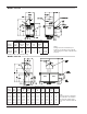
Location of Controls 0400 WH1, WH2, WH3 0181 (LOW NOx) WH1 28
Location of Controls 0824 29
Location of Controls START-UP PROCEDURES Initial Start-Up - Pump and Motor Many pumps are now direct-drive. They have no coupler or bearing assembly. These pumps do not require lubrication. Others require SAE-30 non-detergent oil to lubricate both the motor and the bearing assembly. Check pump motor for type before adding oil.
LIGHTING INSTRUCTIONS FOR HEATERS WITH ELECTRONIC IGNITION (IID) FOR MODELS WITH MANUAL GAS VALVES FOR YOUR SAFETY READ BEFORE OPERATING WARNING:If you do not follow these instructions exactly, a fire or explosion may result causing property damage, personal injury or loss of life. A. This appliance is equipped with an ignition device which automatically lights the pilot. Do not try to light the pilot by hand. B. * * * * BEFORE OPERATING smell all around the appliance area for gas.
FOR MODELS WITH AUTOMATIC GAS VALVES PILOT SHUT-OFF VALVE CONTROL SHOWN IN "ON" POSITION 1. Close all gas valves. Turn off electric power supply. Wait five (5) minutes. 2. Open manual pilot valve. Turn on electric power. Pilot is automatically lighted. 3. Open main gas valve. 4. Set temperature controls to desired temperature. TO SHUT DOWN GAS INLET Close all manual gas valves. Turn off electric power.
ADDENDA: LOW NOx HEATERS MODELS 0181 TO 0401 Inspection Procedures Inspect on the first and third month after initial startup and then on an annual basis. If problems are found, refer to the Troubleshooting sections of this manual for additional directions. The Raytherm Low NOx Heater is offered with WH1On-Off firing (standard) or 2-stage firing (optional). The heaters are certified and tested under the latest edition of the ANSI Z21.10.3/CSA 4.3 standard for hot water heaters.
c. Check the ignition spark operation. Time must be within the lockout timing period (15 or 90 seconds). d. Turn control down to end call for heat and wait 60 seconds on lockout models before beginning step 3. 3. Turn on gas supply. 4. Set controller to call for heat. 5. System should start as follows: a. Spark will turn on and pilot gas valve will open and the blower will begin running. b. Heater will operate until call for heat is satisfied.
Main burner And Orifice Removal 1. Remove burner tray. (See Burner Tray Removal procedure on page 34.) 2. Remove (8) screws from the hold-down brackets. 3. Remove (8) screws from the left and right sides of the manifold assembly. Detach the manifold assembly from the burner tray assembly. 4. Use a long ½” socket wrench to remove orifices from the gas manifold. 5. Remove burners by raising the bracket on the back end of the burners up and out of their slots. 6. Reverse above procedure to re-install. Fig.
TROUbLESHOOTING WARNING—HIGH VOLTAGE: For qualified technicians ONLY. Electrical—Electronic Ignition IID NOTE: Some heaters may be equipped with an ignition module that shuts off pilot gas if pilot fails to light. To reset, interrupt power to heater. Intermittent Pilot System Honeywell S8600 START TURN GAS SUPPLY OFF. TURN THERMOSTAT (CONTROLLER) TO CALL FOR HEAT POWER TO MODULE (24 V NOMINAL)? YES NOTE: Before troubleshooting, familiarize yourself with the start-up and checkout procedure.
Mechanical CORRECTIVE ACTION MECHANICAL PROBLEM POSSIBLE CAUSE When heater is turned on nothing happens. No power to the heater…………………. Check the circuit breaker, outdoor controller, etc., upstream of heater. Bad transformer…………………………. If power to Leads L1 and L2 of transformer, but no power on 24V side, replace. Inoperative thermostat………………….. Jumper thermostat, replace with new if heater fires. Inoperative toggle switch……………….. If power to toggle switch, but not through switch, replace.
WIRING DIAGRAMS Wiring Diagram—W2/WH2 133 38
Wiring Diagram—WH1 0181/0261 39
Wiring Diagram—WH1 0331/0401 40
Wiring Diagram—WH1 0514–0724 41
Wiring Diagram—WH1 0824–1826 42
Wiring Diagram—WH1 2100–2500 43
Wiring Diagram—WH1 3001–4001 44
Troubleshooting—Pumps Pump Loses Prime Failure To Pump 1. 2. 3. 4. 1. 2. 3. 4. Pump not properly primed. Wrong direction of rotation. Speed too low. Total head too high. Air leaks in suction line. Excess air in water. Water seal in stuffing box not functioning. Excessive suction lift and pump operating too near shut-off point. Overloaded Driving Unit Reduced Capacity and/or Head 1. Head much lower than that for which pump is designed. 2. Speed too high or higher than that contemplated. 1. 2. 3. 4.
COMBINATION FLAME SENSOR/ IGNITER AND PILOT BURNER Fig. 38: Typical Burner Tray Illustrated burner Tray Removal 6. Remove the spring and store in a safe place. 7. Using an Allen wrench, turn the screw clockwise to increase or counterclockwise to decrease high fire manifold pressure –see Fig. 39. 8. Install the spring, weight and aluminum cap –tighten the cap using same # of turns as was used in removing the cap. 9.
Main burner and Orifice Removal 8. Lift heat exchanger straight up using caution not to damage refractory. Heat Exchanger Re-Assembly 1. Remove screws and burner hold-down bracket. NOTE: If the heat exchanger is sooted badly, the burner hold-down bracket and spacer can become distorted from direct flame impingement and this usually necessitates replacement of these parts. 2. Lift burners from slotted spacer and slide from orifices. Clean with a wire brush. 3. Orifices usually do not need to be replaced.
Combustion Chamber Removal 9. DO NOT apply excessive torque during rolling operation and avoid thinning any wall of the tube beyond 0.015". 10. Use same procedure on opposite end. 11. Apply line pressure test. Re-roll if necessary. 12. Reinstall as outlined under HEAT EXCHANGER REASSEMBLY. To remove combustion chamber refractory you must first have removed the heat exchanger. Unbolt metal combustion chamber retainer from top and remove refractory panels individually.
LIMITED PARTS WARRANTY RAYTHERM™ COMMERCIAL HEATERS TYPES H & WH MODELS 0133 TO 4001 SCOPE: Raypak, Inc. ("Raypak") warrants to the original owner that all parts of this heater which are actually manufactured by Raypak will be free from failure under normal use and service for the specified warranty periods and subject to the conditions set forth in this Warranty.
www.raypak.com Raypak, Inc., 2151 Eastman Avenue, Oxnard, CA 93030 (805) 278-5300 Fax (805) 278-5468 Litho in U.S.A.