DOM-IOM-6 82-0262 DOMINATOR SERIES FINNED COPPER GAS BOILERS (MODEL DB) & WATER HEATERS (MODEL DW) INSTALLATION & OPERATION MANUAL MEA#117-96-E DESIGNED AND TESTED ACCORDING TO A.S.M.E. BOILER AND PRESSURE VESSEL CODE, SECTION IV FOR A MAXIMUM ALLOWABLE WORKING PRESSURE OF 160 PSI, 1103 kPa WATER. WARNING: If the information in this manual is not followed exactly, a fire or explosion may result causing property damage, personal injury or loss of life.
Page 2 DOMINATOR INSTALLATION AND OPERATION INSTRUCTIONS AVERTISSMENT. Assurez-vous de bien suivre les instructions données dans cette notice pour réduire au minimum le risque d’incendie ou d’explosion ou pour éviter tout dommoge matériel, toute blessure ou la mort Ne pas entreposer ni utiliser d’essence ou ni d’autres vapeurs ou liquides inflammables à proximité de cet appareil ou de tout autre appareil. QUE FAIRE SI VOUS SENTEZ UNE ODEUR DE GAZ: • Ne pas tenter d’allumer d’appareil.
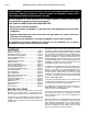
DOMINATOR INSTALLATION AND OPERATION INSTRUCTIONS RATINGS & CAPACITIES Before undertaking the installation of the Dominator Series boiler/water heater check the rating plate to ensure that the unit has been sized properly for the job. The "Net I=B=R Ratings" specify the equivalent amount of direct copper radiation that the unit can supply under normal conditions. Also ensure that the unit has been set up for the type of gas available at the installation site.
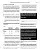
Page 4 DOMINATOR INSTALLATION AND OPERATION INSTRUCTIONS CAUTION: If the boiler/water heater is operated while the building is under construction it MUST be protected from wood, concrete, sheet rock and other types of dust. Failure to properly protect the unit from construction dust will damage the unit voiding the warranty! Buildings will require the installation of a fresh air duct or other means of providing make-up air if the intake air option isn't used.
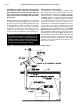
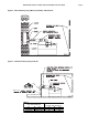
DOMINATOR INSTALLATION AND OPERATION INSTRUCTIONS Figure 2 - Vertical Venting using a Masonry Chimney and Inside Air Figure 3 - Horizontal Venting using Inside Air 1/4 IN. PER F00T 20 mm/m 1.5 FT 0.5 m Table 2 VENT PIPE DIAMETER IN.
Page 6 DOMINATOR INSTALLATION AND OPERATION INSTRUCTIONS All Air From Outside The Building When installed in a confined space without utilizing the intake air option two permanent openings communicating directly with, or by ducts to, the outdoors or spaces that freely communicate with the outdoors must be present. The upper opening must be within 12 in, 305 mm of, but not less than 3 in, 76 mm from, the top of the enclosure.
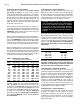
DOMINATOR INSTALLATION AND OPERATION INSTRUCTIONS Page 7 Figure 4 - Horizontal Combustion Air and Venting for a Single Unit 1/4 IN. PER FOOT 20 mm/m 16 FT 4.9 m 1.5 FT 0.
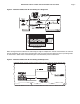
Page 8 DOMINATOR INSTALLATION AND OPERATION INSTRUCTIONS Figure 6 - Vertical Combustion Air and Venting, Metal Chimney System Shown Locate exhaust terminal downwind from air intake to reduce potential for flue gas recirculation. 10 FT 3.1 m 4 FT 1.2 m 5 1/2 FT 1.7 m 1.5 FT 0.5 m 5 FT 1.5 m Figure 7 - Combination Air Intake And Venting, Masonry Chimney Shown 10 FT 3.1 m 3 FT 1 m 1.5 FT .
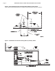
DOMINATOR INSTALLATION AND OPERATION INSTRUCTIONS GENERAL VENTING GUIDELINES Page 9 VENT SYSTEM OPTIONS The Dominator may be vented the following ways: WARNING: The vent installation must be in accordance with Part 7, Venting of Equipment, of the National Fuel Gas Code, ANSI Z223.1/ NFPA 54-latest revision or applicable provisions o f t h e l o c a l bu i l d i n g c o d e s . C a n a d i a n installations must comply with CSA B149.1 or .2 Installation Code.
Page 10 DOMINATOR INSTALLATION AND OPERATION INSTRUCTIONS VERTICAL/CHIMNEY VENTING The Dominator is listed as a Category I appliance when vented vertically into a metal chimney system or properly sized masonry chimney, Figures 1,2, 6 & 7. The chimney must provide a negative pressure of .01 to 0.08 in, .25 to 2.0 mm W.C. at the boiler/water heater flue collar with the unit running at full load. A barometric damper must be installed between the flue collar and the vent connector.
DOMINATOR INSTALLATION AND OPERATION INSTRUCTIONS Page 11 Horizontal vent systems shall terminate at least 4 ft, 1.2 m below, 4 ft, 1.2 m horizontally from or 1 ft, 0.3 m above any door, window or gravity air inlet into any building. It must not terminate less than 4 ft, 1.2 m horizontally from, and in no case above or below, unless a 4 ft, 1.2 m horizontal distance is maintained, from electric meters, gas meters, regulators and relief equipment and not less than 7 ft, 2.
Page 12 DOMINATOR INSTALLATION AND OPERATION INSTRUCTIONS Figure 8 - Outdoor Venting a) Seal any unused openings in the common venting system. Sceller toutes les ouvertures non utilisées du système d'évacuation. b) Visually inspect the venting system for proper size and horizontal pitch and determine there is no blockage or restriction, leakage, corrosion and other deficiencies which could cause an unsafe condition.
DOMINATOR INSTALLATION AND OPERATION INSTRUCTIONS e) Test for spillage at the draft hood relief opening after 5 minutes of main burner operation. Use the flame of a match or candle, or smoke from a cigarette, cigar or pipe. Faire fonctionner le brûleur principal pendant 5 min ensuite, déterminer si le coupe-tirage déborde à l'ouverture de décharge. Utiliser la flamme d'une allunette ou d'une chandelle ou la fumée d'une cigarette, d'un cigare ou d'une pipe.
Page 14 DOMINATOR INSTALLATION AND OPERATION INSTRUCTIONS Relief Valve Pipe the discharge of the pressure relief valve to prevent scalding in the event of a discharge, see Figure 10. The discharge piping must be sized the same as the pressure relief valve outlet and installed to allow complete drainage of both the relief valve and the discharge piping.
DOMINATOR INSTALLATION AND OPERATION INSTRUCTIONS HEATING SYSTEM PIPING General Piping Requirements All heating system piping must be installed by a qualified technician in accordance with the latest revision of the ANSI/ASME Boiler and Pressure Vessel Code, Section IV, and, when required, ANSI/ASME CSD-1, Standard for Controls and Safety Devices for Automatically Fired Boilers. All applicable local codes and ordinances must also be followed.
Page 16 DOMINATOR INSTALLATION AND OPERATION INSTRUCTIONS Figure 11 - Typical Primary/Secondary Piping System (See Notes) Pump Gate Valve Globe Valve NOTES: Angle Valve 1. Boiler circuit piping must be sized large enough to handle maximum flow through unit. 2. Boiler pump sized to boiler design flow requirements. 3. All boilers furnished with factory mounted outlet water temperature gauge. 4. Boiler pump purging required. Use terminals supplied.
DOMINATOR INSTALLATION AND OPERATION INSTRUCTIONS Page 17 Figure 12A - Low Temperature Piping with Thermostatic Piping (See Notes and Adjustment Procedures) Pump Gate Valve Globe Valve Angle Valve NOTES: Bufferfly Valve 1. Boiler circuit piping must be large enough to handle maximum flow through unit. 2. Boiler pump sized to boiler design flow requirements. 3. All boilers furnished with factory mounted outlet water temperature gauge. 4. Boiler pump purging required. Use terminals supplied.
Page 18 DOMINATOR INSTALLATION AND OPERATION INSTRUCTIONS DOMESTIC WATER SUPPLY PIPING CAUTION: Proper control settings must be used to prevent water supplied for domestic use from exceeding 130°F, 54°C or a scald injury will occur! When higher water temperatures are required for appliances such as a dishwasher, a mixing valve or some other tempering means must be installed. Households with small children may require water temperatures less than 120°F, 49°C.
DOMINATOR INSTALLATION AND OPERATION INSTRUCTIONS Table 8A - Dominator Heat Exchanger Selection Graph Table 8B - Dominator Pumping Performance Requirement Page 19
Page 20 DOMINATOR INSTALLATION AND OPERATION INSTRUCTIONS Expansion Tank An expansion tank or other means to control thermal expansion must be installed in the water heating system if back flow prevention devices are installed. Cold Water Supply The cold water supply must be piped to the water heater's outlet piping between the water heater and the hot water storage tank. This will prevent untempered water from entering the water heater, see the Temperature Rise Control section below.
DOMINATOR INSTALLATION AND OPERATION INSTRUCTIONS Figure 14 - Typical Water Heating Piping (DW Models only) (See Notes) Page 21 Pump Valve 3 Globe Valve 1 8 4 Angle Valve 7 Bufferfly Valve 2 Balance Valve D-1 Rev 6 Ball Valve Motorized Valve Attention: Not all RBI stock storage tanks incorporate this tapping: See Note 1.
Page 22 DOMINATOR INSTALLATION AND OPERATION INSTRUCTIONS GAS SUPPLY PIPING WARNING: Check the boiler/water heater rating plate to make sure that the boiler/water heater is for the type of gas that will be used. If it isn’t, do not connect the boiler/water heater to the gas supply. Gas supply piping must be in accordance with the National Fuel Code, ANSI Z223.1-latest revision or applicable provisions of the local building codes. Canadian installations must comply with CAN/CGA B149.1 or .
DOMINATOR INSTALLATION AND OPERATION INSTRUCTIONS WARNING: Never use an open flame to test for gas leaks. Always use an approved leak detection method. Failure to comply with this warning can cause extensive property damage, severe personal injury or death! Whenever the gas supply piping is pressure tested the boiler/water heater gas controls must be protected. If the test pressure is equal to, or less than 1/2 psig, 3.
Page 24 DOMINATOR INSTALLATION AND OPERATION INSTRUCTIONS Start the boiler as described in the “OPERATING INSTRUCTIONS”. Run the boiler for at least an hour. The system pump(s) and all radiation units must be operated during this time. Ensure that the make-up water valve is open. Shut the boiler off and open the bleed valves to purge the air trapped in the heating system piping. Close the make-up water valve and check and clean the strainers and make-up water pressure reducing valve.
DOMINATOR INSTALLATION AND OPERATION INSTRUCTIONS On the four stage units, the left low fire and high fire switches will interrupt power to the control module under a blocked flue or inlet condition. This will cause the pilot and left and right main gas valves to close. The right switches will only shut down the right main gas valve under a blocked flue or inlet condition. The relay board automatically selects between pressure switches as the boiler/water heater changes stages.
Page 26 DOMINATOR INSTALLATION AND OPERATION INSTRUCTIONS 6. If the second ignition attempt is unsuccessful the gas valves will lockout, but the blower, pump and power venter will remain on. To reset the boiler/water heater, take one of the following steps: • Adjust the high limit down below the point at which the blower shuts down, then reset the limit to its normal setting. • Remove power from the boiler/water heater, wait 30 seconds and re-establish power to the unit. 7.
DOMINATOR INSTALLATION AND OPERATION INSTRUCTIONS Page 27 Ignition Trial: 1. Once energized, the flame sense module (FSM) initiates 4 second diagnostic cycle before sending 24V ac to the PV terminal and energizing the ignition transformer. 2. The flame failure LED will be lit during the 4 second diagnostic cycle unless the unit is configured for CSD-1. When the PV terminal energizes, the LED will turn off. If the ignition trial fails, the LED will relight. 3.
Page 28 DOMINATOR INSTALLATION AND OPERATION INSTRUCTIONS OPERATING INSTRUCTIONS FOR YOUR SAFETY READ BEFORE OPERATING POUR VOTRE SÉCURITÉ LISEZ AVANT DE METTRE EN MARCHE A. This appliance is equipped with an ignition device which automatically lights the pilot. Do not try to light the pilot by hand. Cet appareil est muni d'un dispositif d'allumage qui allume automatiquement la veilleuse. Ne tentez pas d'allumer la veilleuse manuellement. B. BEFORE OPERATING smell all around the appliance area for gas.
DOMINATOR INSTALLATION AND OPERATION INSTRUCTIONS 11. Turn the knob on the pilot valve to on, Figure 18. 12. Turn the knob on the main gas valve to on, 300 and 400 models, Figure 18. On 600 through 2100 models open the manual shutoff valve located in the control compartment, Figure 19. 13. Turn on all electric power to the boiler. Page 29 Table 19 - Pilot & Manifold Settings Natural Gas inches W.C. mm W.C. Low Fire 1.5 ± 0.2 33 ± 5 High Fire 2.5 ± 0.2 63 ± 5 LP Gas inches W.C. mm W.C.
Page 30 DOMINATOR INSTALLATION AND OPERATION INSTRUCTIONS CHECKING & ADJUSTMENTS 1. With the burners in operation, close the manual shutoff valve in the gas supply line. As soon as the main burner flames go out, open the manual shutoff valve. A normal ignition sequence should take place. If the burners fail to light, the gas valves will close and the system will go into a 5-minute lock out period. The ignition module will then make a second ignition attempt.
DOMINATOR INSTALLATION AND OPERATION INSTRUCTIONS 4. Use a 3/32 hex wrench to turn the pressure regulator adjustment screw clockwise to increase the pilot pressure and counterclockwise to decrease it. 5. Replace the pressure regulator adjustment screw cap.
Page 32 DOMINATOR INSTALLATION AND OPERATION INSTRUCTIONS High Limit (Aquastat) The high limit is located in the left side area of the boiler/ water heater. A remote capillary bulb is run to a well on the outlet side of the supply header. The high limit can be reset by depressing the black rubber plug in the front top jacket panel. The water heater high limit should be set a minimum of 20°F, 11°C higher than the operating control.
DOMINATOR INSTALLATION AND OPERATION INSTRUCTIONS Mode 3: Domestic Hot Water (DHW) generation. Dominator piped in parallel with the storage tank. DHW demand from sensor located in tank or pool supply pipe. The firing stages are operated to provide a setpoint temperature and maintain DHW tank temperature. DHW OPERATION - The control operates to maintain the programmed tank target temperature at the outlet sensor whenever a DHW demand is present.
Page 34 DOMINATOR INSTALLATION AND OPERATION INSTRUCTIONS MAINTENANCE WARNING: Disconnect electrical power and close the manual gas shut off valve before performing maintenance or severe personal injury may result! WARNING: Improper installation, adjustment, alteration, service or maintenance can cause property damage, personal injury, exposure to hazardous materials or loss of life.
DOMINATOR INSTALLATION AND OPERATION INSTRUCTIONS Heat Exchanger Removal, Cleaning & Replacement See Figure 20 1. Close the shut off valves in the inlet and outlet piping. On heating systems close the system fill valve and relieve the system pressure from the boiler by carefully lifting the relief valve or opening the drain valve. 2. Drain the boiler/water heater and disconnect it from the system piping. 3. Remove the inlet/outlet and return headers. 4. Remove the front jacket panels. 5.
Page 36 DOMINATOR INSTALLATION AND OPERATION INSTRUCTIONS Figure 21 - Heat Exchanger Upper Rail Screws Vent System Thoroughly inspect the vent system for any signs of blockage, corrosion or leakage. Immediately replace any unsound vent system piping. Controls Use the "BOILER/WATER HEATER OPERATION" and "CHECKING AND ADJUSTMENTS" sections of this manual for reference. 1. Check the thermostat or operating controls for proper operation. 2.
DOMINATOR INSTALLATION AND OPERATION INSTRUCTIONS Page 37 Trouble-Shooting PROBLEM No Power To Unit No Action On Call For Heat POSSIBLE CAUSES Power not connected External circuit breaker open Relay board fuse (24V) blown Transformer circuit breaker open (4 stage) Primary limit or other control/interlock open Low water cutoff open Stage control sensor(s) not wired or are malfunctioning No Power To Pump No Power to Power Venter Power Venter On, No Action From Unit Stage control malfunction Pump con
Page 38 DOMINATOR INSTALLATION AND OPERATION INSTRUCTIONS Trouble-Shooting PROBLEM Unit Does Not Spark continued Unit Sparks But Will Not Fire POSSIBLE CAUSES Spark generator fault Low gas pressure Pilot valve manual knob closed Pilot wires disconnected Low pilot pressure Pilot Lights But Unit Will Not Fire Pilot valve malfunctioning Bad flame sense lead from ignitor to flame sense module Manual valve(s) closed Low manifold pressure Insufficient Heating Unit Consistently Shuts Down On Limit Bad Combu
DOMINATOR INSTALLATION AND OPERATION INSTRUCTIONS Page 39 RIOM-22 REV-B Figure 28 - Replacement Parts
Page 40 DOMINATOR INSTALLATION AND OPERATION INSTRUCTIONS SERVICE AND REPLACEMENT PARTS LIST (MODELS 300-2100) Ref # 1 Name of Part Jacket Lower Front Panel Jacket Lower Front Panel (SS) 2 Handle Deckplate Jacket Upper Front Panel Jacket Upper Front Panel (SS) 3 4 5 6 Jacket Left Side Panel Jacket Left Side Panel (SS) Junction Box Assembly Junction Box Cover Jacket Right Panel Jacket Right Panel (SS) 7 Combustion Air Inlet Assembly (Indoor) Combustion Air Inlet Assembly (Outdoor) 8 Filter (Ind
DOMINATOR INSTALLATION AND OPERATION INSTRUCTIONS Ref # 9 Name of Part Jacket Rear Panel Jacket Rear Panel (SS) 11 Jacket Top Panel Jacket Top Panel (SS) Jacket Top Panel (Outdoor) NS 12 13 Outdoor Hood Assembly Base Panel Legs Jacket Base Panel Part # 03-1811 03-1812 03-1813 03-1814 03-1815 03-1816 03-1817 03-1818 03-1819 03-1820 03-1811.1 03-1812.1 03-1813.1 03-1814.1 03-1815.1 03-1816.1 03-1817.1 03-1818.1 03-1819.1 03-1820.
Page 42 Ref # 14 15 16 17 18 19 20 21 22 DOMINATOR INSTALLATION AND OPERATION INSTRUCTIONS Name of Part Combustion Chamber Base Panel Cerablanket Insulation Manning Glass Insulation (per square foot) Combustion Chamber Lower Front Panel Combustion Chamber Upper Front Panel Comb Chamber Lower Left Side Panel Comb Chamber Lower Right Side Panel Comb Chamber Upper Left Side Panel Comb Chamber Upper Right Side Panel Heat Exchanger Guide Rail Combustion Chamber Rear Panel Manning Glass Insulation (pe
DOMINATOR INSTALLATION AND OPERATION INSTRUCTIONS Ref # 23 24, 25, 27 26 28 Name of Part Flue Outlet Assembly Tile Kit End Refractory Panel, Right End Refractory Panel, Left Manifold Left Manifold Right Manifold 29 NS 30 NS NS 31 NS Main Orifice, NG Main Orifice, LP Main Orifice, NG Main Orifice, LP Pilot Orifice, NG Pilot Orifice, LP Pilot Orifice, NG Pilot Orifice, LP Burner Tube Burner Tube w/hole for Pressure Switch Pilot Tube Assembly (tubing and fittings) Burner Gasket Burner Support Rai
Page 44 Ref # NS DOMINATOR INSTALLATION AND OPERATION INSTRUCTIONS Name of Part Heat Exchanger Assembly (Copper) Cast Iron Headers Heat Exchanger Assembly (Copper) Bronze Headers NS Heat Exchanger Assembly (Cupronickel) Cast Iron Headers Heat Exchanger Assembly (Cupronickel) Bronze Headers 32 Tube Bundle (Copper) Tube Bundle (Cupronickel) 34 NS V Baffle Hold-Down Heat Exchanger Support Channel 35 36 O Ring, Inlet/Outlet & Return Headers Stud, Inlet/Outlet & Return Headers ASME Stud, Inlet/Outl
DOMINATOR INSTALLATION AND OPERATION INSTRUCTIONS Ref # 38 39 40 41 42 43 NS NS 44 NS 45 46 47 48 50 NS 51 NS 52 53 NS NS NS 54 NS NS NS NS NS NS NS NS NS NS NS Name of Part Return Header, Bronze Return Header, Cast Iron Inlet/Outlet Header, Bronze Inlet/Outlet Header, Cast Iron Blower, Fasco 7062 Blower, Fasco 7083 Combustion Air Damper Assembly Part # 01-0018S 01-0023S 01-0019S 01-0022S 12-0013 12-0014 70-2818 70-2819 Low Pressure Switch (.30 WC) 14-0059 High Pressure Switch (.
Page 46 Ref # NS NS NS NS NS NS NS NS NS NS NS NS NS NS NS DOMINATOR INSTALLATION AND OPERATION INSTRUCTIONS Name of Part Terminal Block 2P Terminal Block 6P Terminal Block 7P Terminal Block 8P On/Off Switch 2 Amp Fuse PVC Gasket Foam Rating Plate Overlay 2 Stage Overlay 4 Stage Paint Silicone Vent Termination Hood 6" Vent Termination Hood 7" Vent Termination Hood 8" Vent Termination Hood 10" Vent Termination Hood 12" Vent Termination Hood 14" Air Intake Hood 6" Air Intake Hood 8" Air Intake Hood 10"
Page 47 START UP FORM Date of Start Up: Job Name: Model #: Serial Number #: Boiler Model: Dominator Fuel Type: Natural Gas Propane Tech Name System Type: Hydronic Domestic Phone Number Company Name PRE-START UP CHECK LIST ANY VISUAL DAMAGE TO UNIT? INLET FILTER INSTALLED AND CLEAN? PIPING PROPERLY CONNECTED? ALL WIRING CONNECTED PROPERLY? SYSTEM FLOODED AND FLOWING? BOILER PUMP PUMPING INTO INLET? BOILER CIRCULATOR WIRED? COMBUSTION AIR PROVIDED? VENT/STAC
Page 48 COMBUSTION/SAFETY REPORT FACTORY FIRE TEST REPORT: Manifold Gas Pressure: "W.C. Air Differential Pressure: "W.C. FIELD TEST REPORT IN STAGE: Manifold Gas Pressure: "W.C. Air Differential Pressure: "W.C. Pilot Manifold Pressure: "W.C. CO2: Stack Temp. (Net): Efficiency @ °F Inlet Temp. CO (PPM): Stack Draft (Must Be Negative): Pilot Signal: SAFETY CONTROL CHECK: Low Water Cut Off (PPM): Factory Flow Switch Operating Control High Limit Differential Air Switch STG. 1, 2 Differential Air Switch STG.
DOMINATOR INSTALLATION AND OPERATION INSTRUCTIONS NOTICE! Page 49 Commonwealth of Massachusetts Installation Requirements MACODE-3 In the Commonwealth of Massachusetts, the installation must be performed by a licensed plumber or gas fitter. Improper venting can result in excessive levels of carbon monoxide which can cause severe personal injury or death! 1.
Page 50 DOMINATOR INSTALLATION AND OPERATION INSTRUCTIONS
LIMITED WARRANTY Boilers/Water Heaters Industrial, Commercial and Other Non-Residential Use The “Manufacturer” warrants to the original owner at the original installation site that the heat exchanger of the Industrial, Commercial, and other Non-Residential Use Boiler (the “Product”) will be free from defects in material or workmanship for ten (10) years from the date of installation. Additional twenty one (21) year thermal shock warranty on heat exchanger.
260 North Elm Street Westfield, MA 01085 Phone: (413) 568-9571 Fax: (413) 568-9613 7555 Tranmere Drive Mississauga, Ontario L5S 1L4 Canada Phone: (905) 670-5888 Fax: (905) 670-5782