HN-IOM-1 3382-0331 Finned copper tube Gas boilers & Water heaters 500 to 4,000 Btuh Input HeatNet®manual Control adjustment and operation instructions Also read and follow: Futera III Boiler manual or Futera Fusion Boiler manual or Futera XLF Boiler manual This manual is intended only for use by a qualified heating installer/technician. Read and follow this manual, all supplements and related instructional information provided with the boiler.
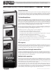
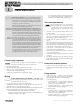
Finned copper tube gas boilers & water heaters – Control manual RBI Futera III/XLF/FUSION-Series boilers — HeatNet control TM Control overview The HeatNet control monitors boiler temperature and limit circuit inputs, modulating boiler firing rate to meet demand. The control uses microprocessor electronics, watching time-average response from the system to anticipate how much heat the system needs. Coupled with the five-to-one turndown of the boiler, this results in maximum operating efficiency.
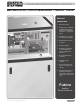
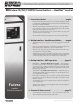
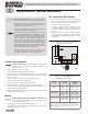
Finned copper tube gas boilers & water heaters – Control manual RBI Futera III/XLF/FUSION-Series boilers — HeatNet control TM Electrical components 6 7 1. Electrical enclosure 2. Control panel — 4-line digital display and navigation buttons (on front of control panel door — see opposite page) 3. On/off switch — on control panel (see opposite page) 4. HeatNet electrical connection panel 5. Electrical subpanel 6.
Finned copper tube gas boilers & water heaters – Control manual RBI Futera III/XLF/FUSION-Series boilers — HeatNet control TM 1 Stand-alone boiler . . . . . . . . . . . . . . . . . . . . . . page 6 • Provide an external contact connected across J12A HEAT DEMAND terminals to start the boiler. (A MEMBER boiler in a network can also be activated by closing the circuit across HEAT DEMAND.) • The boiler can operate based on its SUPPLY temperature, or can be operated by remote control from a 4-20mA source.
Finned copper tube gas boilers & water heaters – Control manual Contents • 4-20mA direct operation — Up to 5 boilers can be controlled by an external control that provides a 4-20ma input signal. The external controls must also activate each boiler by closing a contact across the boiler’s 4-20ma Remote Enable contacts.
Finned copper tube gas boilers & water heaters – Control manual 1 Stand-alone boiler • Electrical shock hazard — Disconnect all electrical power sources to the boiler before making any electrical connections. Label all wires prior to disconnection when servicing controls. Wiring errors can cause improper and dangerous operation! Verify proper operation after servicing. Failure to comply with the above could result in severe personal injury, death or substantial property damage.
Finned copper tube gas boilers & water heaters – Control manual 1 Stand-alone boiler (cont.) c. Call for heat operation PLUS delta temp mode — pump is on during heat calls, during pump postpurge time, and the pump will continue to run after the postpurge timing until the temperature difference across the boiler is less than DELTA TEMP. 4. Flow proving — Flow proving time is adjustable (from 10 to 240 seconds), with factory default setting of 10 seconds.
Finned copper tube gas boilers & water heaters – Control manual 2 Multiple boilers: HeatNet modulation Set termination DIP switches Electrical shock hazard — Disconnect all electrical power sources to the boiler before making any electrical connections. Label all wires prior to disconnection when servicing controls. Wiring errors can cause improper and dangerous operation! Verify proper operation after servicing.
Finned copper tube gas boilers & water heaters – Control manual 2 Multiple boilers: HeatNet modulation (cont.) Pump options Close the external manual gas valve on every boiler before proceeding. DO NOT open any gas valve, or attempt to fire any boiler, until the boilers have been set up and verified following the instructions in the Boiler Installation & Operating Instructions.
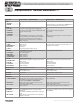
Finned copper tube gas boilers & water heaters – Control manual 2 Table 3 Multiple boilers: HeatNet modulation (cont.) Control parameters for HeatNet networks Parameter Requirement — MASTER boiler BOILERS LEAD STAGE # . . . . . . . . . . . . . HEAT BAND . . . . . . . . . . . . . . . Set Set SETPOINTS LOCAL SETPT . . . . . . . . . . . . . SYSTEM SETPT . . . . . . . . . . . . OPERATE LIMIT . . . . . . . . . . . . OP LIMIT BAND . . . . . .
Finned copper tube gas boilers & water heaters – Control manual 2 Table 3 Multiple boilers: HeatNet modulation (cont.) Control parameters for HeatNet networks (continued) Parameter Requirement — MASTER boiler Requirement — MEMBER boiler DOMESTIC HOT WATER DHW BOILER? . . . . . . . . . . . . . DHW SETPOINT . . . . . . . . . . . DHW DIFF . . . . . . . . . . . . . . . . USE SENSOR? . . . . . . . . . . . . . DHW PRIORITY . . . . . . . . . . . .
Finned copper tube gas boilers & water heaters – Control manual 2 Multiple boilers: HeatNet modulation (cont.) 4. The control’s firmware version number will display. Make sure the firmware of all boilers is compatible. All boilers in a multiple boiler application should preferably have the same firmware version to ensure consistency. If versions are different, all versions must be either version 2.0 or greater, or version 1.x. 3.
Finned copper tube gas boilers & water heaters – Control manual 3 Multiple boilers: BMS operation Option 1: Combined BMS/HeatNet 1. This method uses an RS485 digital communications cable with the MODBUS protocol to control a boiler or HeatNet network. 2. The boiler or boiler network will operate as in the HeatNet local control method (Section 1 of this manual). But, instead of the HEAT DEMAND input, a software form of the HEAT DEMAND input is used (address 40001 — Boiler/ System Enable/Disable). 3.
Finned copper tube gas boilers & water heaters – Control manual Multiple boilers: BMS operation (cont.) BACnet or LonWorks protocols 1. Install the correct protocessor to adapt to building management systems using BACnet or LonWorks protocols. Each boiler must have a protocessor if the BMS is to operate with direct control of each boiler (option 2, page 13). 2. The protocessor translates the BACnet or LonWorks input to the MODBUS protocol for compatibility with the HeatNet controls.
Finned copper tube gas boilers & water heaters – Control manual 4 External 4-20ma control Electrical shock hazard — Disconnect all electrical power sources to the boiler before making any electrical connections. Label all wires prior to disconnection when servicing controls. Wiring errors can cause improper and dangerous operation! Verify proper operation after servicing. Failure to comply with the above could result in severe personal injury, death or substantial property damage.
Finned copper tube gas boilers & water heaters – Control manual 5 Configuring for DHW applications DHW options The HeatNet control allows four options for providing DHW heating. These are: ❑❑ Method 1 — A tank-temperature sensor, connected to the DHW Sensor input allows direct control of tank temperature. Method 1 can be used for combined space heating/DHW systems. This control method is designed to limit tank temperature to a specified maximum. It can cause short cycling in some cases.
Finned copper tube gas boilers & water heaters – Control manual 5 Configuring for DHW applications (continued) Post purge will increase tank temperature above SETPOINT — Adding additional heat to DHW Method 1 — the DHW tank after the setpoint temperature is reached will increase tank temperature ABOVE setpoint. Ensure that this is acceptable. IF NOT, then the pump post purge must be disabled (set to zero).
Finned copper tube gas boilers & water heaters – Control manual 5 Configuring for DHW applications (continued) DHW Method 2 — Tank thermostat control ❑❑ Tank thermostat located in tank. ❑❑ One boiler, master or member if in a network, operated by thermostat closure (across boiler’s OA OVR terminals, J12A terminals 7/8 — see Figure 4, page 23 for location). ❑❑ Dedicated water heating or combined space heating and DHW.
Finned copper tube gas boilers & water heaters – Control manual 5 Configuring for DHW applications (continued) DHW Method 3 — DHW tank sensor (on HEADER Sensor terminals) DHW tank temperature controlled directly — tank temperature sensor (10k thermistor) in tank connected to DHW TEMPERATURE SENSOR input (J10B 1/2) — see Figure 4, page 23 for location. ❑❑ Single or multiple boiler application.
Finned copper tube gas boilers & water heaters – Control manual 6 Wiring Power supply • Header (SYSTEM HEADER) sensor is required — A header sensor (SYS- • Domestic hot water (DHW) sensor — 1. Refer to the Boiler Manual/wiring diagram and rating plate for required voltage and amperage. 2. Connect minimum 14 awg copper wire to the power connection. See Figure 3, page 22. 3. Install a fused service switch, mounted and installed in accordance with all applicable codes.
Finned copper tube gas boilers & water heaters – Control manual 6 Wiring (continued) DHW wiring • • To operate the boiler for domestic water heating with a storage tank, install and pipe the tank according to the tank manufacturer’s instructions and the recommended piping diagrams in the Boiler Installation & Operating Instructions manual. Consult the factory for applications not covered.
Finned copper tube gas boilers & water heaters – Control manual 6 Figure 3 Wiring (continued) HeatNet control field wiring (also see Boiler Installation & Operation Instructions) — Verify against wiring diagram supplied with boiler PUMPS REQUIRE RELAYS OR STARTERS — DO NOT directly operate a pump using the HeatNet contacts. Use these contacts only to operate pump relay or starter coils. 22 P/N HN-IOM-1 82-0331 Copyright 2009 Mestek, Inc.
Finned copper tube gas boilers & water heaters – Control manual 6 Figure 4 Wiring (continued) HeatNet temperature sensors P/N HN-IOM-1 82-0331 Copyright 2009 Mestek, Inc.
Finned copper tube gas boilers & water heaters – Control manual 6 Figure 5 24 Wiring (continued) Field wiring — relays, interlocks and boiler status P/N HN-IOM-1 82-0331 Copyright 2009 Mestek, Inc.
Finned copper tube gas boilers & water heaters – Control manual 6 Figure 6 Wiring (continued) Primary/secondary piping — component electrical connections Component electrical connections 1. Combustion air damper proving switch 2. Combustion air damper motor enable 3. DHW tank sensor (when used in lieu of DHW aquastat) 4. DHW tank aquastat (when used in lieu of DHW sensor) 5. Outdoor air temperature sensor 6. Local flow proving switch 7. System/header temperature sensor 8.
Finned copper tube gas boilers & water heaters – Control manual 6 Figure 7 Wiring (continued) Field wiring connections for 4-20mA remote operation If using a 0–10VDC signal, multiply any references to current in the manual by 0.5. For example: 5ma x 0.5 = 2.5 VDC. 26 P/N HN-IOM-1 82-0331 Copyright 2009 Mestek, Inc.
Finned copper tube gas boilers & water heaters – Control manual 6 Wiring (continued) Figure 8 Field wiring connections for on/off and two-stage firing options P/N HN-IOM-1 82-0331 Copyright 2009 Mestek, Inc.
Finned copper tube gas boilers & water heaters – Control manual 6 Figure 9 28 Wiring (continued) Installation of optional BACnet or LonWorks bridge — Protocessor (for MODBUS operation) P/N HN-IOM-1 82-0331 Copyright 2009 Mestek, Inc.
Finned copper tube gas boilers & water heaters – Control manual 7 Control menus and adjustments The HEATNET control display Starting the display 1. 2. 3. 4. 5. Check all wiring to make sure it is complete and all wires are securely connected. Verify that the HEAT DEMAND and DHW DEMAND wires are removed. Close the external gas valve on every boiler. Turn on power to the boiler and then turn the boiler on/off switch ON.
Finned copper tube gas boilers & water heaters – Control manual 7 Control menus and adjustments (continued) SETUP menus (see Table 9, page 35 for explanations) To enter Setup: From STANDBY, hold for 5 seconds. (If SKIP PASSWORD is set to OFF, you will have to enter the password.) Then press with cursor on SETUP. Make sure there is no call for heat at the boiler before attempting to perform setup adjustments.
Finned copper tube gas boilers & water heaters – Control manual 7 Control menus and adjustments (continued) SETUP menus (continued) (see Table 9, page 35 for explanations) Table 7 Level 1 Level 2 next item next item to select PUMP OPTIONS to select back one level back one level SYSTEM PUMP (Display shows four lines at a time; cursor indicates active line) POST PRG TIME 2M ALWAYS ENABLED OFF SUMMER PUMP JOG:OFF OVR ENAB IN WWS:OFF 2 minutes {1 to 60 minutes} ALWAYS ENABLED OFF {ON or OFF}
Finned copper tube gas boilers & water heaters – Control manual 7 Control menus and adjustments (continued) SETUP menus (continued) (see Table 9, page 35 for explanations) Table 7 Level 1 Level 2 next item next item to select AUX FUNCTIONS to select back one level back one level COMBUST AIR DAMPER FAILSAFE MODES HEAT EXCHANGER SYSTEM CLOCK Default {Range} to change value TYPE LINKED/COMMON {LINKED/COMMON or INDEPENDENT} IN USE? NO {YES or NO} INPUT: J10B “DAMPER” {J10B DAMPER or J12B
Finned copper tube gas boilers & water heaters – Control manual 7 Control menus and adjustments (continued) ADVANCED SETUP menus (see Table 9, page 35 for explanations) To enter Setup: From STANDBY, hold for 5 seconds. (If SKIP PASSWORD is set to OFF, you will have to enter the password.) Then press with cursor on SETUP. Make sure there is no call for heat at the boiler before attempting to perform setup adjustments.
Finned copper tube gas boilers & water heaters – Control manual 7 Control menus and adjustments (continued) ADVANCED SETUP menus (continued) (see Table 9, page 35 for explanations) Table 8 Level 1 Level 2 next item next item to select 4-20MA INPUT LOAD DEFAULTS SYSTEM 34 Default {Range} to select back one level back one level Typical line to change value next item to select to accept value and return to previous menu level 4MA SETPOINT 50°F {50 to 220°F} (Not applied unless SETPOINT
Finned copper tube gas boilers & water heaters – Control manual 7 Table 9 Control menus and adjustments (continued) Setup menus — parameter explanations Menu item Under . . . Explanation FIRMWARE VERSION V X.XX All boilers in a multiple boiler application should preferably have the same firmware version to ensure consistency. If versions are different, they must all have the same first digit in the version number (i.e., 3.x).
Finned copper tube gas boilers & water heaters – Control manual 7 Table 9 Control menus and adjustments (continued) Setup menus — parameter explanations (continued) Menu item Under . . . Explanation OP LIM BAND SETPOINTS If the boiler outlet water temperature rises toward the OPERATE LIMIT setting, the HeatNet control will begin to reduce the boiler’s firing rate when the temperature gets within the limit band degrees F below the operating limit setting.
Finned copper tube gas boilers & water heaters – Control manual 7 Table 9 Control menus and adjustments (continued) Setup menus — parameter explanations (continued) Menu item Under . . . Explanation WWS SETPOINT OUTDOOR AIR The boiler and its circulator shut down when the outside air temperature is above WWS SETPOINT if outdoor air reset is enabled (ON). This requires an outdoor sensor when enabled. The differential is 2°F; i.e.
Finned copper tube gas boilers & water heaters – Control manual 7 Table 9 Control menus and adjustments (continued) Setup menus — parameter explanations (continued) Menu item Under . . . Explanation POST PRGE TIME PUMP OPTIONS LOCAL PUMP The boiler pump can run after boiler shutdown to distribute heat remaining in the boiler water. POST PRGE TIME sets how long the boiler pump will run. (Also see DELTA TEMP, above.
Finned copper tube gas boilers & water heaters – Control manual 7 Table 9 Control menus and adjustments (continued) Setup menus — parameter explanations (continued) Menu item Under . . . Explanation PROOF TIME AUX FUNCTIONS Set proof time long enough to be sure the combustion air damper can open and activate its end switch.
Finned copper tube gas boilers & water heaters – Control manual 7 Table 9 Control menus and adjustments (continued) Setup menus — parameter explanations (continued) Menu item Under . . . Explanation POST PURGE DOMESTIC HOT WATER This is the time that the DHW relay remains on after the DHW call ends. DHW MASTER? DOMESTIC HOT WATER If set to YES, this boiler becomes the MASTER boiler and will use HeatNet to control MEMBER boilers without the use of a header sensor.
Finned copper tube gas boilers & water heaters – Control manual 7 Table 9 Control menus and adjustments (continued) Setup menus — parameter explanations (continued) Menu item Under . . . Explanation Master FIRST ADVANCED SETUP FIRING MODE Set this to “ON” to always start the master boiler first, regardless of the rotation scheme selected.
Finned copper tube gas boilers & water heaters – Control manual 7 Table 9 Control menus and adjustments (continued) Setup menus — parameter explanations (continued) Menu item Under . . . Explanation PRIORITY ADVANCED SETUP When this is set to NORMAL, the priority of a 4-20mA input (when enabled by closure across the 4-20mA enable terminals) is in the normal order: AA (high fire), HEAT DEMAND, HeatNet, 4-20mA, T1/T2.
Finned copper tube gas boilers & water heaters – Control manual 7 Control menus and adjustments (continued) Downloading HeatNet firmware Firmware can be downloaded to the control through the USB port (J6) on the HeatNet control board. You can use either a PC or a flash drive, as explained below. If power is lost (or cycled) while downloading from a flash drive, the download will be corrupted.
Finned copper tube gas boilers & water heaters – Control manual 7 Control menus and adjustments (continued) Calibration of firing rates (blower speeds) This section describes use of the HeatNet control to set blower speeds for minimum input (MIN OUTPUT), maximum input (MAX OUTPUT) and pilot ignition period (IGNITION). Follow all of the instructions in the Boiler Installation and Operation Instructions manual to install and adjust the boiler before proceeding with any of the procedures below.
Finned copper tube gas boilers & water heaters – Control manual 8 Boiler operation and status display Starting the system Follow the Boiler manual — Install the boilers according to the Boiler Installation & Operating Instructions manual before attempting to set up the control system. Perform the start-up and adjustment procedures in the manual before proceeding. Failure to comply could result in severe personal injury, death or substantial property damage.
Finned copper tube gas boilers & water heaters – Control manual 9 Troubleshooting Accessing the data log 1. The log stores major events that have occurred during the operation of the boiler. These events include: • Faults • Boilers starting and stopping • Pump activity • Valve activity (main and pilot) • Input (Type of call for heat) 2.
Finned copper tube gas boilers & water heaters – Control manual 9 Troubleshooting (continued) Table 10 Line #4 log entries Line #4 entry Explanation SETBACK#1 IS ACTIVE SETBACK#2 IS ACTIVE SETBACK#3 IS ACTIVE SETBACK#4 IS ACTIVE If one or more of the setbacks is enabled, these entries will occur when the setback is started or ended.
Finned copper tube gas boilers & water heaters – Control manual 9 Troubleshooting (continued) Table 10 Status screen fault displays (continued) Line #4 entry Explanation OPEN OUTSIDE SENSOR, SUPPLY SENSOR, RETURN SENSOR, HEADER SENSOR, DHW SENSOR This indicates a sensor was detected open or not connected. SHORT OUTSIDE SENSOR, SUPPLY SENSOR, RETURN SENSOR, HEADER SENSOR, DHW SENSOR This indicates a sensor was detected to be shorted.
Finned copper tube gas boilers & water heaters – Control manual 9 Troubleshooting (continued) Fault indications The HeatNet control monitors both boiler and external interlocks, and will shut down the boiler and display a fault code when a problem occurs. See Table 11 for details. Some faults will cause the control to shut down the boiler or system and display the message. CALL FACTORY. Should this message appear, immediately contact RBI for assistance.
Finned copper tube gas boilers & water heaters – Control manual 9 Troubleshooting (continued) Table 11 Status screen fault displays (continued) FAULT EVENT & INTERLOCK TERMINALS GAS PRESSURE (J11A, GAS PR) CAUSE/Discussion Occurs on opening of gas pressure switches connected to J11A GAS PR terminals. The high and low gas pressure switches are wired in series. Opening of either switch will cause this fault.
Finned copper tube gas boilers & water heaters – Control manual 9 Troubleshooting (continued) Table 11 Status screen fault displays (continued) FAULT EVENT & INTERLOCK TERMINALS LOW WATER CUTOFF (J1, LWCO) CAUSE/Discussion DISPLAY Action required to reset from fault Occurs on opening of a low water cutoff switch connected to J11 LWCO terminals. The boiler is shut down until the fault is corrected.
Finned copper tube gas boilers & water heaters – Control manual 9 Troubleshooting (continued) Table 12 Troubleshooting suggestions Situation Suggested procedure Nothing happens when the power switch is turned on. ❑❑ Check 120VAC power on the service connector, J1. Verify power is connected per wiring diagrams. ❑❑ The Power switch light (ON -Position) should illuminate if power is wired correctly.
Finned copper tube gas boilers & water heaters – Control manual 9 Troubleshooting (continued) Table 12 Troubleshooting suggestions (continued) Situation Suggested procedure Unable to change the # of Boilers in the BOILERS menu. ❑❑ In H-Net method, the control auto-detects the boilers in the system and adjusts the number of boilers accordingly. ❑❑ Using H-NET, if the number of boilers is not being detected properly as the actual number of boilers in the system, check each boiler.
Finned copper tube gas boilers & water heaters – Control manual 9 Troubleshooting (continued) Table 12 Troubleshooting suggestions (continued) Situation Suggested procedure You have forgotten the password. ❑❑ Turn the ON/OFF switch off. Then depress and hold the ESC key while turning it back on. This will load the default password “AAAAAA”. Firmware update program starts to load, but then stops. ❑❑ Ensure that the USB driver for your PC/Laptop computer is properly installed.
Finned copper tube gas boilers & water heaters – Control manual 10 Setup worksheet (record all parameters here) SETUP MENU Menu item Default SETUP MENU Value Menu item # OF BOILERS LEAD STAGE # 1 HEAT BAND REMAINS ON: OFF FLOW PROVE 10 seconds NIGHT SETBACK 30°F SETBACK ENTRY SETPOINTS LOCAL SETPOINT 180°F ENTRY IS OPERATE LIMIT 205°F SETBACK OP LIM BAND 10°F SETBACK TIME SETPOINT SOURCE AUTO OUTDOOR AIR RESET OA RESET OFF WARM WEATHER SD NO WWS SETPOINT 68°F WATER TEMP AT
Finned copper tube gas boilers & water heaters – Control manual 10 Setup worksheet (record all parameters here) (continued) SETUP MENU Menu item Default SETUP MENU Value Menu item Default SETBACK LOW TEMP: OFF SETBACK TIME TEMP LESS THAN 40°F START DAY HEAT EXCHANGER TIME ALARM TYPE END DAY EXCHR DELTA T 40°F TIME LIM->HALF RATE YES OPTIONS Value WARNING DOMESTIC HOT WATER TEMP SCALE °F DHW BOILER KEY CLICK ON DHW SETPOINT SKIP PASSWORD ON DHW DIFF 5°F BRIGHTNESS 50%
Finned copper tube gas boilers & water heaters – Control manual 10 Setup worksheet (record all parameters here) (continued) ADVANCED SETUP MENU Menu item Default MODULATE DELAY TIME 50% STOP BAND OFFSET 5°F BOILER START TIME 50 SECONDS Menu item Value 0 MINUTES 10 SECONDS MOD MAX – LAST FIRE ADVANCED SETUP MENU MINUTES CALIBRATED? SENSOR # DROP DOWN DELAY RELEASE 0 SECONDS TYPE Z CALIBRATED? 4-20MA INPUT MODULATION PID Factory set — not adjustable FIRING MODE FIRING MODE TRUE ROTATIO
Finned copper tube gas boilers & water heaters – Control manual Notes 58 P/N HN-IOM-1 82-0331 Copyright 2009 Mestek, Inc.
Finned copper tube gas boilers & water heaters – Control manual Notes P/N HN-IOM-1 82-0331 Copyright 2009 Mestek, Inc.
Finned copper tube gas boilers & water heaters – Control manual 11 Control specifications A MESTEK COMPANY 60 Control Microprocessor based PID modulating control ( NOT a safety limit ) Environment –40 °F to 140 °F < 90% RH non-condensing Input Power 24 VAC, 250 ma Switched Line 120 VAC single phase (120 VAC models only) Relays Stage, Circulator, Alarm 8A 250 VAC AC Interlocks 24 VAC – 120 VAC input Control Inputs AA, Heat Demand, 4-20ma Enable, OA override, T1-T2 (dry contact inputs) Dimen