
Instruction manual

6
P/N HN-IOM-1 82-0331 Copyright 2009 Mestek, Inc.
Finned copper tube gas boilers & water heaters – Control manual
Stand-alone boiler
1
Control setup sequence
Install the boilers according to the Boiler Installation & Operating
Instructions before aempting to set up the control system.
Close the external gas valve.1.
Wire the boiler following the guidelines in this manual.2.
Aach sensors as required, including a HEADER sensor if needed for primary/3.
secondary circuits or DHW tank heating.
Set the boiler control parameters using its display/keypad.4.
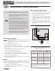
Wiring
PUMPS REQUIRE RELAYS OR STARTERS — DO NOT directly
operate a pump using the HeatNet contacts. Use these contacts only to
operate pump relay or starter coils.
See 1. page 20 for wiring information and wiring diagrams.
Note that the boiler can be wired for override operation. e wiring section pro-2.
vides information on override priorities and options.
e boiler can be activated by the HEAT DEMAND input, and allowed to modu-3.
late based on the HeatNet control. It can also be activated by either:
ON/OFF full input operation by closing the AA terminals.•
Operation via remote 4-20mA signal by closing the 4-20mA ENABLE termi-•
nals and providing the 4-20mA signal.
Electrical shock hazard — Disconnect all electrical power
sources to the boiler before making any electrical connections.
Label all wires prior to disconnection when servicing controls.
Wiring errors can cause improper and dangerous operation!
Verify proper operation aer servicing.
Failure to comply with the above could result in severe personal
injury, death or substantial property damage.
Close the external manual gas valve on every boiler before
proceeding. DO NOT open any gas valve, or aempt to re the
boiler, until the boilers has been set up and veried following the
instructions in the Boiler Installation & Operating Instructions.
Failure to comply could cause a boiler failure, leading to possible
severe personal injury, death or substantial property damage.
e electrical connections to this boiler must be made in
accordance with all applicable local codes and the latest revision
of the National Electrical Code, ANSI /NFPA-70. Installation
should also conform to CSA C22.1 Canadian Electrical Code
Part I if installed in Canada. Install a separate 120 volt 15 amp
circuit for the boiler. A properly rated shut-o switch should be
located at the boiler. e boiler must be grounded in accordance
with the authority having jurisdiction, or if none, the latest
revision of the National Electrical Code, ANSI/NFPA-70.
Line voltage eld wiring of any controls or other devices must
use copper conductors with a minimum size of #14 awg. Use
appropriate wiring materials for units installed outdoors.
Two-stage red by using the T1 and T2 terminals. Clos-•
ing one of these brings the boiler on at MIN ring rate.
Closing the other brings the boiler to MAX input.
Set control parameters
Before turning boilers on to set parameters,
disconnect all call for heat wiring at the electrical
connection boards. is will prevent the boiler
from aempting to cycle during the setup
process.
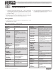
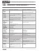
See 1. Table 1 for a list of parameters that should be set for a
stand-alone boiler.
See “2. Control menus and adjustments,” beginning on
page 29 for a complete list of control parameters and expla-
nations (Table 7, page 30 and Table 8, page 33).
Carefully read the parameter explanations in 3. Table 9,
page 35.
When adjusting the limit band, operating limit (OP LIM-4.
IT), local setpoint (LOC SETPOINT), system header or
DHW setpoint, make sure the operating temperature bands
do not overlap or cause potential for nuisance cycling.
System clock — Set the system clock to ensure the time 5.
stamps will be accurate in the data logs.
Turn on the power to the boiler and set the on/o switch to 6.
ON as you set its parameters.
Use the boiler’s keypad to enter the parameters as described 7.
on page 29.
Aer seing a boiler’s parameters, turn o the power to the 8.
boiler until you are ready to start the boiler up following the
Boiler manual instructions.
Domestic hot water options
Read the options and explanations given on 1. page 16
through page 19 to determine the best conguration for the
system.
Pump options
Summer pump jog — enable to operate the circulator 1.
pump once per week (at 12:01 AM on any specied day)
when the heater is shut down for summer shutdown.
System pump options:2.
Constant circulation — pump remains on at all times a.
unless outdoor reset is enabled and the outdoor tem-
perature is above WWS SETPOINT.
Operation on call for heat — pump is on only during b.
heat calls and during pump postpurge time.
Local pump options:3.
Constant circulation — pump remains on at all times a.
unless outdoor reset is enabled and the outdoor tem-
perature is above WWS SETPOINT.
Operation on call for heat — pump is on only during b.
heat calls and during pump postpurge time.