
Instruction manual

8
P/N HN-IOM-1 82-0331 Copyright 2009 Mestek, Inc.
Finned copper tube gas boilers & water heaters – Control manual
Multiple boilers: HeatNet modulation
2
Control setup sequence
Follow the Boiler manual — Install the boilers according to the Boiler
Installation & Operating Instructions
manual before aempting to set up
the control system.
Close the external gas valve on every boiler.1.
Wire all boilers following the guidelines in this manual.2.
Aach a header sensor (SYSTEM HEADER terminals) to the master boiler 3.
ONLY. e HeatNet control automatically congures the boiler with a header
sensor as the master.
Set the master boiler control parameters using its display/keypad.4.
Set the master boiler’s termination DIP switches.5.
Set the termination DIP switches on the member boilers.6.
Set the member boilers’ control parameters using their display/keypads.7.
Follow the instructions in the Boiler Installation & Operating Instructions to start 8.
up each boiler before proceeding further.
Finish by connecting cables between the communications boards of all of the boil-9.
ers and verifying network operation.
Wiring
PUMPS REQUIRE RELAYS OR STARTERS — DO NOT directly
operate a pump using the HeatNet contacts. Use these contacts only to
operate pump relay or starter coils.
See page 1. page 20 for wiring information and wiring diagrams.
Note that the boilers can be wired for override operation. e wiring section pro-2.
vides information on override priorities.
Electrical shock hazard — Disconnect all electrical power
sources to the boiler before making any electrical connections.
Label all wires prior to disconnection when servicing controls.
Wiring errors can cause improper and dangerous operation!
Verify proper operation aer servicing.
Failure to comply with the above could result in severe personal
injury, death or substantial property damage.
e electrical connections to this boiler must be made in
accordance with all applicable local codes and the latest revision
of the National Electrical Code, ANSI /NFPA-70. Installation
should also conform to CSA C22.1 Canadian Electrical Code
Part I if installed in Canada. Install power supplies to the
boiler as indicated on the boiler wiring diagram, making sure
to provide the correct voltage, phase and amperage capacity
specied. A properly rated shut-o switch should be located at
the boiler. e boiler must be grounded in accordance with the
authority having jurisdiction, or if none, the latest revision of
the National Electrical Code, ANSI/NFPA-70.
Line voltage eld wiring of any controls or other devices must
use copper conductors with a minimum size of #14 awg. Use
appropriate wiring materials for units installed outdoors.
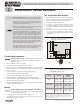
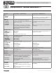
Set termination DIP switches
e HeatNet network needs to recognize the beginning 1.
and end of the network. is requires seing the four DIP
switches on each boiler’s electrical connection board.
See 2. Figure 1 for location of the switches.
See 3. Table 2 for required seings. e table gives seings
for HeatNet modulation — local control and for remote
control from a building management system (MODBUS
protocol).
DO NOT connect the communications cables (or shielded 4.
wires) between boilers until all boilers have had parameters
set and then been started up following all instructions in the
Boiler manual.
Termination DIP switches (located at lower Figure 1
left corner of control board) (component
details are omitted for clarity)
Termination DIP switch settings (HeatNet Table 2
switches are on left, MODBUS switches are on
right) (DOWN = ON; UP = OFF)
Boiler HeatNet MODBUS
(see note)
Master Switch 1: ON
Switch 2: ON
Switch 1: ON
Switch 2: ON
Last member Switch 1: ON
Switch 2: ON
Switch 1: ON
Switch 2: ON
Other members Switch 1: OFF
Switch 2: OFF
Switch 1: OFF
Switch 2: OFF
Note: MODBUS setup is for applications controlled by a building
management system. For systems using BACnet or LonWorks, a bridge
board is used to interface with the HeatNet control. If each boiler is directly
controlled by the BMS, set the DIP switches for each boiler the same as for a
master boiler (both switches on).