
Instruction manual

9
P/N HN-IOM-1 82-0331 Copyright 2009 Mestek, Inc.
Finned copper tube gas boilers & water heaters – Control manual
Set control parameters
Before turning boilers on to set parameters,
disconnect all call for heat wiring at the electrical
connection boards. is will prevent the boiler
from aempting to cycle during the setup
process.
See “1. Control menus and adjustments,” beginning on
page 29 for a complete list of control parameters and expla-
nations (Table 7, page 30 and Table 8, page 33).
Carefully read the parameter explanations in 2. Table 9,
page 35.
When adjusting the limit band, operating limit (OP LIM-3.
IT), local setpoint (LOC SETPOINT) and DHW setpoint,
make sure the operating temperature bands do not overlap
or cause potential for nuisance cycling.
System clock — Set the system clock on the master boiler 4.
ONLY, to ensure the time stamps will be accurate in the
data logs.
Turn on the power to each boiler and set the on/o switch 5.
to ON as you set its parameters.
Use the boiler’s keypad to enter the parameters as described 6.
on page 29.
Aer seing a boiler’s parameters, turn o the power to the 7.
boiler until you are ready to start the boiler, following the
Boiler manual instructions.
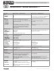
Set the master boiler and each member boiler, following the 8.
guidelines given in Table 3.
Domestic hot water options
Read the options and explanations given on 1. page 16
through page 19 to determine the best conguration for the
system.
Close the external manual gas valve
on every boiler
before proceeding. DO
NOT open any gas valve, or aempt to
re any boiler, until the boilers have
been set up and veried following the
instructions in the Boiler Installation &
Operating Instructions.
Failure to comply could cause a boiler
failure, leading to possible severe
personal injury, death or substantial
property damage.
Multiple boilers: HeatNet modulation (cont.)
2
Pump options
Summer pump jog — enable to operate the circulator 1.
pump once per week (at 12:01 AM on any specied day)
when the heater is shut down for summer shutdown.
System pump options:2.
Constant circulation — pump remains on at all times a.
unless outdoor reset is enabled and the outdoor tem-
perature is above WWS SETPOINT.
Operation on call for heat — pump is on only during b.
heat calls and during pump postpurge time.
Local pump options:3.
Constant circulation — pump remains on at all times a.
unless outdoor reset is enabled and the outdoor tem-
perature is above WWS SETPOINT.
Operation on call for heat — pump is on only during b.
heat calls and during pump postpurge time.
Call for heat operation PLUS delta temp mode — c.
pump is on during heat calls, during pump postpurge
time, and the pump will continue to run aer the post-
purge timing until the temperature dierence across
the boiler is less than DELTA TEMP.
Flow proving — Flow proving time is adjustable (from 10 4.
to 240 seconds), with factory default seing of 10 seconds.
Adjust this time if necessary to compensate for slow-open-
ing valves or other factors that would delay ow start.
Start up boilers per boiler I & OM
Turn o power to all boilers.1.
Follow all instructions in the Boiler Installation & Oper-2.
ating Instructions to start up each boiler and verify opera-
tion.
Connect network cables
Electrical shock hazard — Turn o power
to each boiler before aempting to connect the
network cables.
Before turning boilers on to check network
operation, disconnect all call for heat wiring at the
electrical connection boards. is will prevent
the boiler from aempting to cycle during the
setup process.
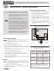
Master boiler cable
Connect an RJ45 cable to the master boiler H-Link OUT 1.
block (Figure 3, page 22) or 3-wire shielded cable to the H-
Link terminal strip (Figure 3, page 22). e other end of this
cable will be aached to the rst member boiler in following
steps.
Turn on power to the master boiler and set its on/o switch 2.
to ON.
You should hear at least 2 beeps.3.