XLF-I0M-2 82-0317 Finned copper tube Gas boilers (MB) & Water heaters (MW) Boiler manual Installation and operation instructions Also read and follow: XLF HeatNet Control manual This manual is intended only for use by a qualified heating installer/technician. Read and follow this manual, all supplements and related instructional information provided with the boiler. Install, start and service the boiler only in the sequence and methods given in these instructions.
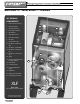
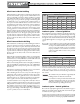
Finned F d copper tube b gas boilers b l & water heaters h – Boiler B l Manual M l RBI Futera XLF-Series boilers — Overview XLF PRIMARY COMPONENTS 1 1. Electrical enclosure (rear) 2. Blower and motor 10 3. Air inlet connection 11 4. Flue outlet connection 12 5. Gas entrance 6. Boiler water return 7. Boiler water supply 8. Gas valve 9. Power entrance box 13 14 15 2 10. DP switch — blocked air inlet 11. DP switch — blocked flue 12. DP switch — blower proving 18 13.
Finned F d copper tube b gas boilers b l & water heaters h – Boiler B l Manual M l BEFORE YOU START . . . . . . . . . . . . . . . . . . . . 3 RATINGS & CAPACITIES . . . . . . . . . . . . . . . . . . 4 BOILER/WATER HEATER LOCATION . . . . . . . . . . . . 4 COMBUSTION AIR & VENTILATION . . . . . . . . . . . . . 4 GENERAL VENTING GUIDELINES. . . . . . . . . . . . . . 6 EXISTING COMMON VENT SYSTEMS . . . . . . . . . . . 6 VENT SYSTEM OPTIONS . . . . . . . . . . . . . . . . . .
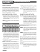
Finned F d copper tube b gas boilers b l & water heaters h – Boiler B l Manual M l RATINGS & CAPACITIES Before undertaking the installation of the Futera XLF Series boiler/ water heater check the rating plate to ensure that the unit has been sized properly for the job. The “Net I=B=R Ratings” specify the equivalent amount of direct cast iron radiation that the unit can supply under normal conditions. Also ensure that the unit has been set up for the type of gas available at the installation site.
Finned F d copper tube b gas boilers b l & water heaters h – Boiler B l Manual M l All air from inside the building If the Futera XLF is to be located in a confined space, the minimum clearances listed in Table 1, page 4 must be maintained between it and any combustible construction. When installed in a confined space without the intake air option (as in Figure 5, page 10 through Figure 8, page 13) two permanent openings communicating with an additional room(s) are required.
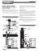
Finned F d copper tube b gas boilers b l & water heaters h – Boiler B l Manual M l Intake air option – Horizontal guidelines The maximum equivalent length for the horizontal intake air pipe is 100 ft, 30.5 m. Each 90o elbow and the intake air terminal are equal to 10 linear ft, 3.0 m of pipe. If horizontal runs exceed 5 ft, 1.5 m they must be supported at 3 ft, 0.9 m intervals with overhead hangers.
Finned F d copper tube b gas boilers b l & water heaters h – Boiler B l Manual M l 3. OPTION 3 — Side Wall Vent, Positive Pressure Category IV (individual venting only) (page 11) Combustion air is obtained from the space in which the unit is installed. Vent system is certified to UL 1738 for installations in the United States, ULC S636 for installations in Canada. Maximum equivalent length of vent and air piping must not exceed 100 feet each.
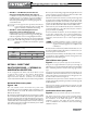
Finned F d copper tube b gas boilers b l & water heaters h – Boiler B l Manual M l Figure 1 VENT OPTION 1: DIRECT VENT — Horizontal air intake and venting for a single direct vent system Vent pipe and air pipe equivalent lengths must not exceed 100 feet each. See Table 3 or 4 for min. pipe diameters.
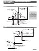
Finned F d copper tube b gas boilers b l & water heaters h – Boiler B l Manual M l Figure 4 VENT OPTION 1: DIRECT VENT — Vertical air intake and venting for direct vent system Vent pipe and air pipe equivalent lengths must not exceed 100 feet each. See Table 3 or 4 for min. pipe diameters. Locate exhaust terminal downwind from air intake to reduce potential for flue gas recirculation. Failure to comply could result in severe personal injury or death.
Finned F d copper tube b gas boilers b l & water heaters h – Boiler B l Manual M l OPTION 2: VERTICAL VENTING POSITIVE PRESSURE, CATEGORY IV FIGURE 5 OR FIGURE 6 lined and sized. Exterior masonry chimneys should not be used unless properly lined to prevent condensation and draft problems. Table 4 lists the equivalent breeching and flue sizes required for the boiler/water heater.
Finned F d copper tube b gas boilers b l & water heaters h – Boiler B l Manual M l OPTION 3: SIDE WALL VENTING POSITIVE PRESSURE —CATEGORY IV FIGURE 7 (VENT/AIR PIPE EQUIVALENT LENGTHS UP TO 100 FEET MAXIMUM) In this configuration the boiler/water heater blower is used to push the flue products horizontally to the outdoors, see Figure 7. The air for combustion is taken from the space in which the unit is installed.
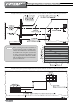
Finned F d copper tube b gas boilers b l & water heaters h – Boiler B l Manual M l OPTION 4: VERTICAL CHIMNEY VENTING NEGATIVE PRESSURE — CATEGORY II CATEGORY II CHIMNEY INSPECTION & SIZING (MULTIPLE BOILERS WITH COMMON VENTING) Masonry chimneys, when used, must be lined with a metal liner certified for Category IV venting. FIGURE 8 Category II venting is required for multiple XLF boilers connected to a common vent. Common vent systems cannot be pressurized.
Finned F d copper tube b gas boilers b l & water heaters h – Boiler B l Manual M l Figure 8 OPTION 4: VERTICAL CHIMNEY VENTING — Vertical venting — multiple-boiler installations See Table 5, page 12 for minimum riser diameter (dimension F) DO NOT common vent more than the following number of Futera XLF boilers: XLF-2500/3000 (4) boilers maximum. XLF-3500/4000 (3) boilers maximum. Legend for Figure 8 The boiler nearest the vertical chimney must always be fired first. A negative pressure of 0.02 to 0.
Finned F d copper tube b gas boilers b l & water heaters h – Boiler B l Manual M l GENERAL PIPING REQUIREMENTS Improper piping of this boiler/water heater will void the manufacturer’s warranty and can cause boiler failure resulting in flooding and extensive property damage! Excessive water hardness causing scaling in the copper heat exchanger tubes is NOT covered under the manufacturer’s warranty. See Table 8, page 20.
Finned F d copper tube b gas boilers b l & water heaters h – Boiler B l Manual M l A temperature rise outside of the range listed in Table 7 will result in damage to the heat exchanger, voiding the warranty! The maximum allowable temperature rise through the boiler is 35oF, 19.4oC. Figure 9 The maximum allowable flow rate through a Futera XLF boiler is 260 GPM, 16.4 L/s when equipped with copper tubes. A cupronickel heat exchanger allows for 315 GPM, 19.9 L/s.
Finned F d copper tube b gas boilers b l & water heaters h – Boiler B l Manual M l Table 7 Primary/secondary piping Temperature Rise Table Model Number ΔT = 20oF ΔT = 11.1oC Flow Rate Pres. Drop Flow Rate Pres. Drop GPM Ft L/s kPa 2500 217.5 10.05 13.7 29.6 3000 261.0 15.20 16.5 44.8 3500 304.5* 20.26 19.2* 59.7 4000 NA NA NA NA Model Number ΔT = 25oF Flow Rate ΔT = 13.9oC Pres. Drop Flow Rate Pres. Drop GPM Ft L/s kPa 2500 174.0 6.45 11.0 19.0 3000 208.
Finned F d copper tube b gas boilers b l & water heaters h – Boiler B l Manual M l Figure 10 Typical Primary/Secondary Piping System (See Notes) NOTES: 1. Boiler circuit piping must be sized large enough to handle maximum flow through unit. 2. Boiler pump sized to boiler design flow requirements. 3. All boilers furnished with factory mounted outlet water temperature gauge. 4. Boiler pump purging required. Use terminals supplied.
Finned F d copper tube b gas boilers b l & water heaters h – Boiler B l Manual M l Figure 12 Low Temperature Piping (See Notes and Adjustment Procedures) H-3 Rev 5 Figure 13 Multiple Boiler Piping (See notes) These drawings show suggested piping configuration and valving. Check with local codes and ordinances for specific requirements. NOTES: 1. Boiler circuit piping must be large enough to handle maximum flow through unit. H-15 Rev 4 2. Boiler pump sized to boiler design flow requirements. 3.
Finned F d copper tube b gas boilers b l & water heaters h – Boiler B l Manual M l DOMESTIC WATER SUPPLY PIPING Proper controls must be used to prevent water supplied for domestic use from exceeding 130oF, 54oC or a scald injury will occur! When higher water temperatures are required for appliances such as a dishwasher, a mixing valve or some other tempering means must be installed. Households with small children may require water temperatures less than 120oF, 49oC.
Finned F d copper tube b gas boilers b l & water heaters h – Boiler B l Manual M l Selection Table (Table 8) and the Pumping Performance Table (Table 9). Scale free operation can be achieved by using water with a hardness between 8 and 18 and by maintaining the pH between 5 and 9. Follow the conditions listed under NORMAL in the table. In some areas of the country additional precautions must be observed due to unusual characteristics of the local water supply.
Finned F d copper tube b gas boilers b l & water heaters h – Boiler B l Manual M l Figure 14 Figure 15 Typical Water Heating Piping (MW Models Only) (See Notes) Multiple Water Heating Piping (MW Models Only) (See Notes) These drawings show suggested piping configuration and valving. Check with local codes and ordinances for specific requirements. NOTES: 1. Optional cold water make up and recirculation line location. 2.
Finned F d copper tube b gas boilers b l & water heaters h – Boiler B l Manual M l GAS SUPPLY PIPING Figure 16 Gas Supply Piping Check the boiler/water heater rating plate to make sure that the boiler/water heater is for the type of gas that will be used. If it isn’t, do not connect the boiler/water heater to the gas supply. Gas supply piping must be in accordance with the National Fuel Code, ANSI Z223.1-latest revision or applicable provisions of the local building codes.
Finned F d copper tube b gas boilers b l & water heaters h – Boiler B l Manual M l ELECTRICAL WIRING Table 11 Equivalent length (feet) for typical fittings Pipe size 90o elbow Tee (branch flow) Electrical power connections Fitting or valve Gate valve Gas cock 2" 5.2 10.3 1.2 3.0 2½" 6.2 12.3 1.4 3.5 3" 7.7 15.3 1.8 4.5 4" 10.1 20.2 2.4 6.0 5" 12.6 25.2 2.9 7.3 6" 15.2 30.4 3.5 13.4 Equivalent lengths above are for threaded fittings. Multiply values above by 0.
Finned F d copper tube b gas boilers b l & water heaters h – Boiler B l Manual M l GENERAL OPERATION WIRING & CONTROL SET-UP Before proceeding read and fully understand the instructions contained in this manual. Do not attempt to operate this boiler/water heater if it has not been installed in accordance with the guidelines set forth in this manual.
Finned F d copper tube b gas boilers b l & water heaters h – Boiler B l Manual M l Figure 17 HeatNet Control Panel SEQUENCE OF OPERATION NO DEMAND Standby 1. The boiler is idle with no interlocks in the fault condition. DEMAND Pre-Purge 1. The blower operates at purge RPM. The water flow interlock must ‘make’ within 15 seconds after the demand signal is initiated. 2. The Honeywell 7800 starts a 10 second purge delay once the air prove switch contacts close. Pilot Run - %Input 1.
Finned F d copper tube b gas boilers b l & water heaters h – Boiler B l Manual M l The following start-up procedure assumes that all water piping, gas piping and electrical connections are correct as stated in this manual and the installation meets all State, Local, and City codes. See the Futera XLF Control IOM for troubleshooting information and control operation. b.
Finned F d copper tube b gas boilers b l & water heaters h – Boiler B l Manual M l Verify low fire operation 1. Connect a manometer or Magnehelic gauge with the pressure side to the manifold pressure port and the other to the manifold reference port. See Figure 18, page 26 for locations. 2. Set Honeywell R7800 control to RUN position. The boiler will operate at low fire because the low fire switch is in the low fire position. 3. Measure the flue gas CO2 with the boiler running at low fire.
Finned F d copper tube b gas boilers b l & water heaters h – Boiler B l Manual M l 6. If CO2 and pressure signal are correct, allow the boiler to reach steady state and verify supply gas pressure and check input rates as explained in the Gas Supply Piping section. 7. Remove jumper on AA and allow boiler to settle into minimum input. Observe the combustion readings to ensure the boiler is operating correctly. 8. When finished, disable the low fire hold switch and replace test ports to normal state.
Finned F d copper tube b gas boilers b l & water heaters h – Boiler B l Manual M l Pilot adjustment 1. The pilot pressure has been factory set at 3 inches w.c., and shouldn't need adjustment. a. With the boiler powered, generate a call for heat. b. When the prepurge is complete the ignition/pilot trial will begin. 2. To adjust the pilot the following steps must be taken: a. Put the Honeywell RM7800 test switch in the test position.
Finned F d copper tube b gas boilers b l & water heaters h – Boiler B l Manual M l MAINTENANCE Disconnect electrical power and close the manual gas shut off valve before performing maintenance or severe personal injury may result! Servicing, inspection and adjustment must be done by a trained technician in accordance with all applicable local and national codes.
Finned F d copper tube b gas boilers b l & water heaters h – Boiler B l Manual M l 6. Replace the pipe plugs using a suitable thread sealant on each one. 7. Sagging or distorted heat exchanger tubes are an indication of low water flow through the system. A damaged heat exchanger must be replaced and the condition that caused the damage resolved before the boiler/water heater is returned to service. 8. Replace the heat exchanger and other components in the reverse order of their removal.
Finned F d copper tube b gas boilers b l & water heaters h – Boiler B l Manual M l Figure 23 32 Futera XLF pressure sensor hose routing
Finned F d copper tube b gas boilers b l & water heaters h – Boiler B l Manual M l REPAIR PARTS Figure 24 Exploded view 33
Finned F d copper tube b gas boilers b l & water heaters h – Boiler B l Manual M l REPAIR PARTS (CONTINUED) Figure 25 34 Figure 20 – Electrical components
Finned F d copper tube b gas boilers b l & water heaters h – Boiler B l Manual M l REPAIR PARTS (CONTINUED) Model Size with item Quantities Below Ref # Name of Part Part # 2500 3000 3500 4000 1 Top/Bottom X Profile 04-0524 3 3 3 3 2 Middle X Profile 04-0526 2 2 2 2 3 Top Y Profile 04-0530 4 4 4 4 4 Bottom Y Profile 04-0535 4 4 4 4 04-0537 5 Top/Bottom Z Profile 04-0539 4 4 4 4 6 Middle Z Profile 04-0541 2 2 2 2 7 Bottom/Front X Profile 04-0528 1 1 1 1 8
Finned F d copper tube b gas boilers b l & water heaters h – Boiler B l Manual M l REPAIR PARTS (CONTINUED) Model Size with item Quantities Below Ref # Name of Part NS Manifold/Orifice Mounting Plate (Forward) Manifold/Orifice Mounting Plate (Rear) Part # 2500 3000 3500 4000 03-3734 1 03-3721 1 1 1 03-3728 1 1 1 1 1 1 2 2 2 25 Mixing Box Gasket 06-0080 1 NS Gas Injectors, NG 10-1005 1 10-1002 26 Flow Switch 14-0203 1 1 1 1 70-2413.
Finned F d copper tube b gas boilers b l & water heaters h – Boiler B l Manual M l REPAIR PARTS (CONTINUED) Model Size with item Quantities Below Ref # Name of Part 37 Combustion Chamber Rear/Side Panel Part # 2500 70-3566 1 70-3567 3000 3500 1 70-3568 1 70-3569 38 1 Manning Glass Insulation (per square foot) 05-0104 24 Combustion Chamber Door Assembly 70-3572 1 70-3573 24 26 26 1 70-3574 1 70-3575 39 4000 1 Manning Glass Insulation (per square foot) 05-0104 7 7 7 7 Pres
Finned F d copper tube b gas boilers b l & water heaters h – Boiler B l Manual M l REPAIR PARTS (CONTINUED) Model Size with item Quantities Below Ref # Name of Part Part # 2500 3000 3500 4000 48 Frequency Drive 15-0230 1 1 1 1 49 Flame Safeguard, RM7895C 16-0024R 1 1 1 1 50 Spark Ignitor 16-0008 1 1 1 1 51 Air Pressure Switch 11-0419 1 1 1 1 52 Fan Prove Switch 11-0420 1 1 1 1 11-0419 1 1 1 1 03-3752 1 1 1 1 NS Mounting Bracket 53 Transformer, 50 VA 15
Finned F d copper tube b gas boilers b l & water heaters h – Boiler B l Manual M l REPAIR PARTS (CONTINUED) Model Size with item Quantities Below Ref # Name of Part Part # 2500 3000 3500 4000 59 Control Box Panel 70-3609 1 1 1 1 60 Collar Fan Transition 01-0201S 1 1 1 1 60a Gasket 06-0004 1 1 1 1 60b Fan Hold Down Plate 04-0596 1 1 1 1 62 Mini Fan 12-0021 1 1 1 1 63 Air Funnel 04-1016 1 1 1 1 64 Solenoid Valve w/Regulator, NG 11-0372 1 1 1 1 Solenoid V
Finned F d copper tube b gas boilers b l & water heaters h – Boiler B l Manual M l START-UP REPORT DATE: JOB NAME: TECHNICIAN: LOCATION: COMPANY: MODEL: PHONE NUMBER: SERIAL #: PRE-STARTUP CHECK LIST ❑ ❑ ❑ ❑ NO VISIBLE DAMAGE TO UNIT PIPING PROPERLY CONNECTED BOILER CIRCULATOR WIRED VENT/STACK CONNECTED ❑ ❑ ❑ ❑ INLET AIR FILTER INSTALLED AND CLEAN PROPER SERVICE CLEARANCES PROVIDED PUMP RUNNING, HEAT EXCHANGER FULL GAS LINES PURGED, NO LEAKS, NO MISSING TEST PLUGS BOILER STARTUP SEQUENCE Note:
Finned F d copper tube b gas boilers b l & water heaters h – Boiler B l Manual M l COMBUSTION ANALYSIS MINIMUM FIRING RATE GAS PRESSURE AT ELBOW TEST PORT 100% FIRING RATE INCHES W.C. INCHES W.C. CO2 % % O2 % % PPM PPM CO (PPM) o NET STACK TEMPERATURE PRESSURE SIGNAL (Ps) o F F INCHES W.C. INCHES W.C.
Finned F d copper tube b gas boilers b l & water heaters h – Boiler B l Manual M l NOTICE! Commonwealth of Massachusetts Installation Requirements In the Commonwealth of Massachusetts, the installation must be performed by a licensed plumber or gas fitter. 1.
LIMITED WARRANTY Boilers/Water Heaters Industrial, Commercial and Other Non-Residential Use The “Manufacturer” warrants to the original owner at the original installation site that the heat exchanger of the Industrial, Commercial, and other Non-Residential Use Boiler (the “Product”) will be free from defects in material or workmanship for ten (10) years from the date of installation. Additional twenty one (21) year thermal shock warranty on heat exchanger.
260 North Elm Street 7555 Tranmere Drive Westfield, MA 01085 Mississauga, Ontario L5S 1L4 Canada Phone: (413) 568-9571 Phone: (905) 670-5888 Fax: (413) 568-9613 Fax: (905) 670-5782 www.rbiwaterheaters.com 44 Copyright 2008 Mestek, Inc.