MODELS: LB/LW-500, 750 AND 1000 SERIES 400/401 GAS-FIRED POWER BURNER COPPER BOILERS FOR HYDRONIC HEATING AND HOT WATER SUPPLY • INSTALLATION • OPERATION • MAINTENANCE • LIMITED WARRANTY H WARNING: If the information in this manual is not followed exactly, a fire or explosion may result causing property damage, personal injury or loss of life. — Do not store or use gasoline or other flammable vapors and liquids in the vicinity of this or any other appliance.
ROUGH-IN DIMENSIONS Minimum clearances to combustibles: • 4” (102 mm) rear • 0” (0 mm) top & sides • 6” (152 mm) vent TABLE 1, GAS AND ELECTRICAL CHARACTERISTICS Manifold Pressure Maximum Supply Pressure Electrical Characteristics Model Type of Gas Inches W.C. kPa Inches W.C. kPa Volts/Hz Amperes LB/LW-500, 750, 1000 NATURAL 3.5 0.87 13.8 3.44 120/60 30 LB/LW-500, 750, 1000 PROPANE 10 2.49 13.8 3.44 120/60 30 Minimum Supply Pressure, Natural Gas: 7.0 inches W.C. (1.
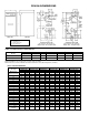
ROUGH-IN DIMENSIONS (Continued) TABLE 3, RECOVERY CAPACITIES U.S.
CONTENTS Page Page ROUGH-IN DIMENSIONS .............................................................. 2-3 FOREWORD .................................................................................. 4 Grounding Instructions ............................................................. 5 Inlet Water Considerations ........................................................ 5 Correct Gas ............................................................................. 5 Precautions .................................
These are available from the Canadian Standards Association, 8501 East Pleasant Valley Road, Cleveland, OH 44131, USA, or, Canadian Gas Association Laboratories, 55 Scarsdale Road, Don Mills, Ontario M3B 2R3, Canada. with age. For these reasons, the use of a propane gas detector is recommended. IF YOU EXPERIENCE AN OUT OF GAS SITUATION, DO NOT TRY TO RELIGHT APPLIANCES YOURSELF. Call your local service agent.
system monitors the burner flame through the principle of flame rectification. If a flame is not verified, the gas valve is immediately closed. NOTE: Some gas utility companies derate their gas for altitude, making it unnecessary to install high altitude orifices. Call the local gas utility company to verify BTU content.
AIR SHUTTER the BFS, the main burner is extinguished (if boiler is running) or the boiler will not start up. The blower is equipped with an air shutter assembly for fine adjustment of the air to gas ratio The assembly consists of a shutter flange and the air shutter. The shutter may require adjustment to achieve ideal start-up characteristics when fine tuning the boiler for correct combustion specifications. Refer to the Start-Up Procedures, part number 192077 Rev.
CIRCULATING PUMP DRAIN VALVE HOT WATER SUPPLY SYSTEMS, the circulating pump is integral to the LW models. This pump has been lubricated at the factory, and future lubrication should be in accordance with the motor manufacturer’s instructions provided as a supplement to this manual. A drain valve is factory installed in the heat exchanger manifold. This will help to drain the heat exchanger.
If the boiler is installed above radiation level, a Low Water Cutoff Device must be installed in the boiler outlet at the time of installation. The T & P relief valve must comply with the applicable construction provisions of the Standard for Relief Valves and Automatic Gas Shutoff Devices for Hot Water Supply Systems, ANSI Z21.22-1999 or CAN/CSA-B149.1-00, or most recent edition. The T & P relief valve must be of the automatic reset type and not embody a singleuse type fusible plug, cartridge or linkage.
or spaces freely communicating with the outdoors. The installation instructions for confined spaces in tightly constructed buildings must be followed to ensure adequate air supply. Where power vented equipment is used in the same room as the boiler, sufficient air openings must be supplied. UNDERSIZED OPENINGS MAY RESULT IN INSUFFICIENT AIR FOR COMBUSTION. CONFINED SPACE A. U.S.
2. AL 29-4C® sections and fittings MUST be used for the entire length of the exhaust system; alternatives such as galvanized pipe, PVC, CPVC or Type B Vent sections must not be used. consideration is recommended, before locating the vent termination near walkways, windows and building entrances. Direct venting into dead spaces such as; alleys, atriums and inside corners can cause recirculation of flue gases.
NOTES: If the exhaust vent terminal is within 10’ (3.0 m) of a wall or parapet, it must extend a minimum of 2’ (610 mm) above the wall or parapet. Joints are not joined to show vent pipe orientation. FIGURE 9. VERTICAL TERMINATION NOTES: Joints are not joined to show vent pipe orientation. FIGURE 9A.
The Boot-Tee Drain Cover is required in order to dispose of the condensate from the venting system. The plastic tube (3/8 [9 mm] ID, 10 feet [3 m] long) needed to route the condensate to a suitable drain is provided with the boiler. DO NOT rivet or screw the straps to the conduit or otherwise puncture the conduit wall. Instead, wrap an extra loop of strap around the conduit to hold it in position, or attach the strap to the center screw of the double wall AL 29-4C® vent coupling, if applicable. 1.
NOTE: Joints are not joined to show vent pipe orientation. FIGURE 11. DIRECT VENT HORIZONTAL CAUTION Direct venting into dead air spaces such as; alleys, atriums and inside corners can cause recirculation of flue gases. Recirculation of flue gases will cause sooting, premature failure of the heat exchanger and icing of the combustion air intake during severe cold weather.
Option B (Figures 11B & 11C) assures no recirculation of flue gases. 90 EQUIVALENT FEET (27.4M) OF VENTING (MAX.) AL 29-4C AIR INTAKE TERMINAL HORIZONTAL AIR INTAKE NOTES: PVC PIPE 90 EQUIVALENT FEET (27.4M) • IF THE EXHAUST VENT TERMINAL IS WITHIN 10’ (3.0M) OF A WALL OR A PARAPET, IT MIUST EXTEND A MINIMUM OF 2’ (0.6M) ABOVE THE WALL OR PARAPET. • ON SIDEWALL VENT INSTALLATION, REFER TO FIGURE 7 FOR SPACING SPECIFICATIONS • FOR EXHAUST AND AIR INTAKE PIPE INSTALLATIONS (CLEARANCES, SUPPORT, ETC.
TWT shall not be greater than ninety (90) equivalent feet [27.4 m] of vent pipe nor less than nine (9) feet [3 m] (excluding fittings) unless the vent is through a non-combustible wall. A maximum of three (3) 90° degree elbows may be used. For standard installations where no air intake piping is included, the total distance can be extended to 180 equivalent feet [54.9 m] with a maximum of five (5) 90° degree elbows. Standard minimum horizontal vent length is three (3) feet [1.0 m].
DANGER TEMPERATURE SETTING SHOULD NOT EXCEED SAFE USE TEMPERATURE AT FIXTURES. SEE WATER TEMPERATURE CONTROL WARNING ON PAGE 28. IF HIGHER PREHEAT TEMPERATURES ARE NECESSARY TO OBTAIN ADEQUATE BOOSTER OUTPUT, ADD AN ANTI-SCALD VALVE FOR HOT WATER SUPPLIED TO FIXTURES. • INSTALL IN ACCORDANCE WITH ALL LOCAL CODES. • WHEN BLOW DOWN VALVE IS REQUIRED, INSTALL IN PLACE OF THE DRAIN VALVE SHOWN. FIGURE 12.
ONE LEGEND (MODEL LW) HOT WATER SUPPLY BOILER WITH VERTICAL TANK DANGER TEMPERATURE SETTING SHOULD NOT EXCEED SAFE USE TEMPERATURE AT FIXTURES. SEE WATER TEMPERATURE CONTROL WARNING ON PAGE 28. IF HIGHER PREHEAT TEMPERATURES ARE NECESSARY TO OBTAIN ADEQUATE BOOSTER OUTPUT, ADD AN ANTI-SCALD VALVE FOR HOT WATER SUPPLIED TO FIXTURES. INSTALL THERMAL EXPANSION TANK ON COLD WATER SUPPLY LINE, IF CHECK VALVE OR PRESSURE REDUCING VALVE IS USED IN SUPPLY. FIGURE 13.
HARD WATER CONDITIONS TANK PROBE SET-POINT ADJUSTMENT Where hard water conditions exist, water softening or the threshold type of water treatment is recommended. This will protect the dishwashers, coffee urns, water heaters, water piping and other equipment. When water softening or water treatment is not practical, a comparatively easy method of periodic lime removal from the unit may be employed.
Size of gas supply piping may be larger than heater connection on installations where a significant run of piping is required. To prevent damage, care must be taken not to apply too much torque when attaching gas supply pipe to boiler gas inlet. Fittings and unions in the gas line must be of the metal to metal type. Apply joint compounds (pipe dope) sparingly and only to the male threads of pipe joints. Do not apply compound to the first two threads.
10 (3.05) 20 (6.1) 680,000 465,000 199 136 1,400,000 950,000 410 278 2,100,000 1,460,000 615 428 3,950,000 2,750,000 1,157 805 6,300,000 4,350,000 1,845 1,274 11,000,000 7,700,000 3,222 2,255 23,000,000 15,800,000 6,736 4,627 Maximum Capacity of Pipe in BTU/hr and kW for Gas Pressures of 14 in. W.C. (0.5 psi) or Less and a Pressure Drop of 0.5 in. W.C. (based on 0.60 Specific Gravity Gas w/Heating Value of 1,000 BTU's/Ft3) Length of Pipe in Feet (Meters) 30 (9.14) 40 (12.19) 50 (15.24) 60 (18.
FIGURE 16.
FIGURE 17 - SCHEMATIC DIAGRAM 23
VERIFY PROPER OPERATION AFTER SERVICING. STRICT ADHERENCE TO THE WIRING DIAGRAMS IS REQUIRED TO PREVENT CONSTANT PUMP OPERATION WHEN THE SYSTEM CONTROLLER IS SATISFIED. OTHERWISE THE WARRANTY IS VOID AS STIPULATED IN THE LIMITED WARRANTY IN THIS INSTALLATION MANUAL. Lighting and Operating instructions are included with this manual. By using these instructions, the user may be able to make minor operational adjustments and save unnecessary service calls.
LIGHTING & OPERATION INSTRUCTIONS FOR MODELS LB/LW-500 ONLY: FOR YOUR SAFETY READ BEFORE OPERATING WARNING: IF YOU DO NOT FOLLOW THESE INSTRUCTIONS EXACTLY, A FIRE OR EXPLOSION MAY RESULT CAUSING PROPERTY DAMAGE, PERSONAL INJURY OR LOSS OF LIFE. A. THIS APPLIANCE DOES NOT HAVE A PILOT. IT IS EQUIPPED WITH AN IGNITION DEVICE WHICH AUTOMATICALLY LIGHTS THE BURNER. DO NOT TRY TO LIGHT THE BURNER BY HAND. B. BEFORE LIGHTING: SMELL ALL AROUND THE APPLIANCE AREA FOR GAS.
LIGHTING & OPERATION INSTRUCTIONS FOR MODELS LB/LW-750 AND 1000 ONLY: FOR YOUR SAFETY READ BEFORE OPERATING WARNING: IF YOU DO NOT FOLLOW THESE INSTRUCTIONS EXACTLY, A FIRE OR EXPLOSION MAY RESULT CAUSING PROPERTY DAMAGE, PERSONAL INJURY OR LOSS OF LIFE. A. THIS APPLIANCE DOES NOT HAVE A PILOT. IT IS EQUIPPED WITH AN IGNITION DEVICE WHICH AUTOMATICALLY LIGHTS THE BURNER. DO NOT TRY TO LIGHT THE BURNER BY HAND. B. BEFORE LIGHTING: SMELL ALL AROUND THE APPLIANCE AREA FOR GAS.
in the combustion chamber to clear. IF YOU DETECT GAS ODOR AT THE END OF THIS PERIOD DO NOT PROCEED WITH LIGHTING. RECOGNIZE THAT GAS EVEN IF IT SEEMS WEAK, MAY INDICATE PRESENCE OF ACCUMULATED GAS SOMEPLACE IN THE AREA WITH RISK OF FIRE OR EXPLOSION. SEE THE FRONT PAGE FOR STEPS TO BE TAKEN. INLET GAS PRESSURE The inlet gas pressure is measured at the main manual gas shut-off valve, which is upstream of the unit’s gas valves and pressure regulators. The maximum supply pressure of 13.8 inches W.C. (3.
FOR LB/LW-750 AND LB/LW-1000 MODELS: energy efficient operation of the boiler and minimize scale formation in the heat exchanger, thus prolonging the life of the boiler. 1. Manually shut off the gas supply by one of the two methods. On boilers that have a manual shutoff valve downstream from the automatic gas valves, turn the manual shut off valve to the “OFF” position.
every six months. All relief valves should be inspected and manually operated at least twice a year. 2. If the ignition control determines the actual water temperature at the outlet temperature sensing probe is below the programmed temperature set-point less the switching differential, and the thermostat circuit is closed, a call for heat is activated.
Flame pattern should have hard, uniform blue flames surrounding the burner, see figure 19. 9. Restore electrical power and gas supply to the boiler. • Put the boiler back in operation by following the Lighting and Operating instructions in this manual. If the flame is pulsing, floating, yellow and/or lifting off the burner, check the manifold gas pressure and combustion air supply; maintain a clear area around the boiler at all times. • Check for gas leaks and proper boiler and vent operation.
24-Volt method of temperature control, the J33 jumper must be removed and the red/green wires in the junction box at the rear of the unit must be used. (see figure 21 and 22). Standard LB models will not have a jumper across the J33 board leads. Wires are provided in the junction box for a 24-Volt method of temperature control. LINE POLARITY INDICATOR A green LED is mounted on the ignition control board to indicate line voltage polarity is properly connected.
If the ADJUST push-button is held down long enough, the setpoint will reach 110°F [43°C], the minimum value (or 240°F [115°C], the maximum value) and stop. At this point, if the desired setting is not obtained, release the ADJUST push-button and depress it again. The set-point value will now restart at 110°F [43°C] (240°F [115°C]) and once again increase (decrease) in value for as long as the ADJUST push-button is pressed.
Table 10. value (or 50°F [28°C], the maximum value) and stop. At this point, if the desired switching differential is not obtained, release the ADJUST push-button and depress it again. The switching differential value will now start at 5°F (3°C) to (50°F [28°C]) and once again increase (decrease) in value for as long as the ADJUST push-button is pressed.
If the ADJUST push-button is held down long enough, the set-point will reach 110°F (43°C), the minimum value (or 190°F [88°C], the maximum value) and stop. At this point, if the desired set-point is not obtained, release the ADJUST push-button and depress it again. The set-point value will now restart at 110°F (43°C) to 190°F [88°C] and once again increase (decrease) in value for as long as the ADJUST push-button is pressed.
NOTE: Under certain circumstances, a problem with the low gas pressure switch (and/or high gas pressure switch on CSD-1 models) may cause an error code of Circulation FAIL or Inducor FAIL depending on when the failure occurred in the cycle. – The display defaults to the outlet water temperature under normal circumstances. On LW models, however, the display defaults to the tank probe temperature once the probe supplied with the unit is connected to the control board.
LIMITED WARRANTY A. O. Smith Corporation, the warrantor, extends the following LIMITED WARRANTY to the owner of this boiler: 1. If within TEN years after initial installation of the boiler, a coiled heat exchanger or gas burner shall prove upon examination by the warrantor to be defective in material or workmanship, the warrantor, at his option will exchange or repair such part or portion. This term is reduced to FIVE years if this boiler is used for water heating purposes other than hydronic space heating.