SPMIOM-5 82-0255 SPECTRUM FINNED COPPER GAS BOILERS (MODEL SB) & WATER HEATERS (MODEL SW) INSTALLATION & OPERATION MANUAL DESIGNED AND TESTED ACCORDING TO A.S.M.E. BOILER AND PRESSURE VESSEL CODE, SECTION IV FOR A MAXIMUM ALLOWABLE WORKING PRESSURE OF 160 PSI, 1103 kPa WATER WARNING: If the information in this manual is not followed exactly, a fire or explosion may result causing property damage, personal injury or loss of life.
Page 2 SPECTRUM INSTALLATION AND OPERATING INSTRUCTIONS AVERTISSMENT. Assurez-vous de bien suivre les instructions données dans cette notice pour réduire au minimum le risque d’incendie ou d’explosion ou pour éviter tout dommoge matériel, toute blessure ou la mort Ne pas entreposer ni utiliser d’essence ou ni d’autres vapeurs ou liquides inflammables à proximité de cet appareil ou de tout autre appareil. QUE FAIRE SI VOUS SENTEZ UNE ODEUR DE GAZ: • Ne pas tenter d’allumer d’appareil.
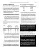
SPECTRUM INSTALLATION AND OPERATING INSTRUCTIONS RATINGS & CAPACITIES Before undertaking the installation of the Spectrum boiler/water heater check the rating plate to ensure that the unit has been sized properly for the job. The "Net I=B=R Ratings" specify the equivalent amount of direct cast iron radiation that the unit can supply under normal conditions. Also ensure that the unit has been set up for the type of gas available at the installation site.
Page 4 SPECTRUM INSTALLATION AND OPERATING INSTRUCTIONS To operate properly and safely this boiler/water heater requires a continuous supply of air for combustion. NEVER store objects on or around the boiler/water heater! Where communicating with the outdoors through horizontal ducts, each opening shall have a minimum free area of 1 in2/2000 Btu/hr, 1100 mm2/kW of the total input rating of all of the equipment in the enclosure.
SPECTRUM INSTALLATION AND OPERATING INSTRUCTIONS Chimney Inspection & Sizing A thorough inspection of the masonry chimney must be performed to ensure that the chimney is clean, properly constructed, lined and sized. Exterior masonry chimneys should not be used unless properly lined to prevent condensation and draft problems. Table 4 lists the equivalent breeching and flue sizes required for the boiler/water heater.
Page 6 SPECTRUM INSTALLATION AND OPERATING INSTRUCTIONS c) Insofar as is practical, close all building doors and windows and all doors between the space in which the appliances remaining connected to the common venting system are located and other spaces of the building. Turn on clothes dryers and any appliance not connected to the common venting system. Turn on any exhaust fans, such as range hoods and bathroom exhaust, so they will operate at maximum speed.
SPECTRUM INSTALLATION AND OPERATING INSTRUCTIONS Page 7 Figure 1 - Vertical Venting with a Metal Chimney System and Inside Air 10 FT 3.
Page 8 SPECTRUM INSTALLATION AND OPERATING INSTRUCTIONS GENERAL PIPING REQUIREMENTS OUTDOOR VENTING When installed outdoors the Spectrum must be fitted with the factory supplied outdoor hood assembly, see Figure 3. Multiple units must be spaced per Figure 3A. The boiler/water heater must be at least 10 ft, 3.1 m from any door, window or gravity air inlet into any building and at least 3 ft, 0.9 m from any overhang unless local codes dictate differently.
SPECTRUM INSTALLATION AND OPERATING INSTRUCTIONS Relief Valve Pipe the discharge of the pressure relief valve to prevent scalding in the event of a discharge, see Figure 4. The discharge piping must be sized the same as the pressure relief valve outlet and installed to allow complete drainage of both the relief valve and the discharge piping. Page 9 The thermal expansion of the system must be considered when supporting the system. A minimum system pressure of 12 psig, 82.7 kPa must be maintained.
Page 10 SPECTRUM INSTALLATION AND OPERATING INSTRUCTIONS Table 7 - Temperature Rise Table – 2 Pass Headers ΔT = 10°F ΔT = 5.5°C ΔT = 20°F ΔT = 11.1°C ΔT = 30°F ΔT = 16.7°C Model Number Flow Rate Pres. Drop Flow Rate Pres. Drop Flow Rate Pres. Drop Flow Rate Pres. Drop Flow Rate Pres. Drop Flow Rate Pres. Drop GPM Ft L/s kPa GPM Ft L/s kPa GPM Ft L/s kPa 100 16.4 0.05 1.0 0.1 — — — — — — — — 150 24.6 0.13 1.6 0.4 — — — — — — — — 200 32.4 0.27 2.
SPECTRUM INSTALLATION AND OPERATING INSTRUCTIONS Page 11 Figure 5 - Typical Primary/Secondary Piping System (See Notes) Pump Gate Valve Globe Valve 1 NOTES: Angle Valve 1. Boiler circuit piping must be sized large enough to handle maximum flow through unit. 2. Boiler pump sized to boiler design flow requirements. 3. All boilers furnished with factory mounted outlet water temperature gauge. 4. Boiler pump purging required. Use terminals supplied.
Page 12 SPECTRUM INSTALLATION AND OPERATING INSTRUCTIONS Figure 6A - Low Temperature Piping (See Notes and Adjustment Procedures) Pump Gate Valve Globe Valve 1 Angle Valve Adjustment Procedure To Maintain Inlet Temperature Above Dew Point T1-Temp-Min+110° For Atmospheric T1-Temp-Min=125° Sealed Combusion Bufferfly Valve Balance Valve 1. Turn heater on and open valves A & B. 2.
SPECTRUM INSTALLATION AND OPERATING INSTRUCTIONS Variable Water Flows Figure 5 shows a typical primary/secondary piping system. A dedicated pump is used to maintain a constant water flow through the boiler. This boiler pump is sized to overcome the head loss of the boiler and near piping while supplying the flow rate required to maintain the desired temperature rise across the boiler heat exchanger. The system pump is sized to provide the required flow to the heating system.
Page 14 SPECTRUM INSTALLATION AND OPERATING INSTRUCTIONS RBI water heaters are designed to run scale free. Due to the extreme variables of water conditions world wide it is necessary to consider pH values and water hardness in relationship to scaling. It is crucial to consider these two variables when making heat exchanger and pump selections. If local water conditions are extreme follow the guidelines in the Heat Exchanger Selection Table (Table 9A) and the Pumping Performance Table (Table 9B).
SPECTRUM INSTALLATION AND OPERATING INSTRUCTIONS Table 9A - Spectrum Heat Exchanger Selection Graph Table 9B - Spectrum Pumping Performance Requirement Table Page 15
Page 16 SPECTRUM INSTALLATION AND OPERATING INSTRUCTIONS Figure 8 - Typical Water Heating Piping (MW Models Only) (See Notes) Pump Valve 3 Globe Valve 1 8 4 Angle Valve 7 Bufferfly Valve 2 Balance Valve D-1 Rev 6 Ball Valve Motorized Valve Attention: Not all RBI stock storage tanks incorporate this tapping: See Note 1.
SPECTRUM INSTALLATION AND OPERATING INSTRUCTIONS GAS SUPPLY PIPING Page 17 Table 11 - Equivalent Pipe Length WARNING: Check the boiler/water heater rating plate to make sure that the boiler/water heater is for the type of gas that will be used. If it isn’t, do not connect the boiler/water heater to the gas supply. Gas supply piping must be in accordance with the National Fuel Code, ANSI Z223.1-latest revision or applicable provisions of the local building codes.
Page 18 SPECTRUM INSTALLATION AND OPERATING INSTRUCTIONS When applicable, provisions for vent, bleed and gas relief lines must be made in accordance with the latest revision of ANSI Z223.1/NFPA 54. ELECTRICAL WIRING Safe lighting and other performance criteria were met with the gas manifold and control assembly provided on the boiler. All gas connections MUST be leak tested before putting the boiler into operation. CAUTION: Label all wires prior to disconnection when servicing controls.
SPECTRUM INSTALLATION AND OPERATING INSTRUCTIONS GENERAL OPERATION WARNING: Before proceeding read and fully understand the instructions contained in this manual. Do not attempt to operate this boiler/ water heater if it has not been installed in accordance with the guidelines set forth in this manual.
Page 20 SPECTRUM INSTALLATION AND OPERATING INSTRUCTIONS FOR YOUR SAFETY READ BEFORE LIGHTING WARNING: If you do not follow these instructions exactly, a fire or explosion may result causing property damage, personal injury or loss of life. A. If this appliance is equipped with a continuous pilot, it must be lit by hand. Follow the lighting instructions exactly. B. BEFORE LIGHTING smell all around the appliance area for gas.
SPECTRUM INSTALLATION AND OPERATING INSTRUCTIONS Page 21 FOR YOUR SAFETY READ BEFORE OPERATING WARNING: If you do not follow these instructions exactly, a fire or explosion may result causing property damage, personal injury or loss of life. A. If this appliance is equipped with an electronic ignition device, this automatically lights the burner. Do not try to light the burner by hand. B. BEFORE OPERATING smell all around the appliance area for gas.
Page 22 SPECTRUM INSTALLATION AND OPERATING INSTRUCTIONS CHECKING & ADJUSTMENTS Pilot Adjustment The pilot burner flame should envelope 3/8 in to 1/2 in, 9.5 mm to 12.7 mm of the flame sensing probe, Figure 11. To adjust the pilot the following steps must be taken: 1. Remove the pilot gas pressure regulator cap. 2. Turn the pressure regulator adjustment screw clockwise to decrease the flame and counterclockwise to increase it. 3. Replace the pressure regulator adjustment screw cap.
SPECTRUM INSTALLATION AND OPERATING INSTRUCTIONS Avoid placing the thermostat in areas that will not provide an accurate measurement of the room temperature. Locating the thermostat behind a door, in an alcove, close to a source of thermal radiation or in a drafty area will cause poor or sporadic heating. For a thermostat that employs an adjustable heat anticipator, adjust the anticipator to match the current measured in the thermostat circuit.
Page 24 SPECTRUM INSTALLATION AND OPERATING INSTRUCTIONS Figure 12 - Burner Drawer Assembly 2. A damaged heat exchanger must be replaced and the condition that caused the damage resolved before the boiler/water heater is returned to service. Vent System Thoroughly inspect the vent system for any signs of blockage, corrosion or leakage. Immediately replace any unsound vent system piping. RIOM-55 Combustion Chamber Inspection 1. Remove the burner drawer following the instructions above. 2.
SPECTRUM INSTALLATION AND OPERATING INSTRUCTIONS Page 25 Figure 14 - Replacement Parts 17 11 9 7 23 18 5 10 2 30 37 36 8 20 21 3 35 34 31 33 4 12 32 14 19 25 28 24 22 4 13 1 6 27 16 26 15
Page 26 SPECTRUM INSTALLATION AND OPERATING INSTRUCTIONS SERVICE AND REPLACEMENT PARTS LIST (MODELS 100-400) Model Size With Item Quantities Below Ref # 1 Name of Part Part No.
SPECTRUM INSTALLATION AND OPERATING INSTRUCTIONS Page 27 Model Size With Item Quantities Below Ref # Name of Part Part No.
Page 28 SPECTRUM INSTALLATION AND OPERATING INSTRUCTIONS Model Size With Item Quantities Below Ref # 9 Name of Part Part No.
SPECTRUM INSTALLATION AND OPERATING INSTRUCTIONS Page 29 Model Size With Item Quantities Below Ref # 17 Name of Part Part No.
Page 30 SPECTRUM INSTALLATION AND OPERATING INSTRUCTIONS Model Size With Item Quantities Below Ref # 25 Name of Part Part No.
SPECTRUM INSTALLATION AND OPERATING INSTRUCTIONS Page 31 OPTIONS Model Size With Item Quantities Below Ref # Name of Part Part No.
Page 32 SPECTRUM INSTALLATION AND OPERATING INSTRUCTIONS MACODE-3 NOTICE! Commonwealth of Massachusetts Installation Requirements (a) For all side wall horizontally vented gas fueled equipment installed in every dwelling, building or structure used in whole or in part for residential purposes, including those owned or operated by the commonwealth and where the side wall exhaust vent termination is less than seven (7) feet above finished grade, in the area of the venting, including but not limited to decks
SPECTRUM INSTALLATION AND OPERATING INSTRUCTIONS Page 33 MACODE-3 NOTICE! Commonwealth of Massachusetts Installation Requirements In the Commonwealth of Massachusetts, the installation must be performed by a licensed plumber or gas fitter. (b) Exemptions The following equipment is exempt from 248 CMR 5.08(2)(a) 1 through 4: 1. The equipment listed in Chapter 10 entitled “Equipment Not Required To Be Vented” in the most current edition of NFPA 54 as adopted by the Board; and 2.
LIMITED WARRANTY Boilers/Water Heaters Industrial, Commercial and Other Non-Residential Use The “Manufacturer” warrants to the original owner at the original installation site that the heat exchanger of the Industrial, Commercial, and other Non-Residential Use Boiler (the “Product”) will be free from defects in material or workmanship for ten (10) years from the date of installation. Additional twenty one (21) year thermal shock warranty on heat exchanger.
SPECTRUM INSTALLATION AND OPERATING INSTRUCTIONS Page 35
260 North Elm Street Westfield, MA 01085 Phone: (413) 568-9571 Fax: (413) 568-9613 7555 Tranmere Drive Mississauga, Ontario L5S 1L4 Phone: (905) 670-5888 Fax: (905) 670-5782