IE8000-R1 High Efficiency Condensing Stainless Steel Gas Hot Water Supply Boiler Models IEW-199, IEW-399 Boiler manual Installation and operation instructions CONTROLS 260 North Elm Street Westfield, MA 01085 Tel: (413) 568-9571 Fax: (413) 568-9613 7555 Tranmere Drive Mississauga, ONT. L5S IL4 Canada Tel: (905) 670-5888 Fax: (905) 670-5782 www.rbiwaterheaters.com Copyright 2011 Mestek, Inc.
TABLE OF CONTENTS TABLE OF CONTENTS USING THIS MANUAL 1 A. INSTALLATION SEQUENCE . . . . . . . . . . . . . .1 B. SPECIAL ATTENTION BOXES . . . . . . . . . . . . .1 1. PREINSTALLATION 2 A. GENERAL . . . . . . . . . . . . . . . . . . . . . . . . . . . . .2 B. CODES & REGULATIONS . . . . . . . . . . . . . . . .2 C. ACCESSIBILITY CLEARANCES . . . . . . . . . . . .3 D. COMBUSTION & VENTILATION AIR . . . . . . . .3 E. PLANNING THE LAYOUT . . . . . . . . . . . . . . . .6 2. BOILER SET-UP 7 A. GENERAL . . . . . .
USING THIS MANUAL USING THIS MANUAL A. INSTALLATION SEQUENCE Follow the installation instructions provided in this manual in the order shown. The order of these instructions has been set in order to provide the installer with a logical sequence of steps that will minimize potential interferences and maximize safety during boiler installation. DANGER Indicates a condition or hazard which will cause severe personal injury, death or major property damage. WARNING B.
PREINSTALLATION 1. PREINSTALLATION A. GENERAL 1. Infinite Energy boilers are supplied completely assembled as packaged boilers. The package should be inspected for damage upon receipt and any damage to the unit should be reported to the shipping company and wholesaler. This boiler should be stored in a clean, dry area. 2. Carefully read these instructions and be sure to understand the function of all connections prior to beginning installation.
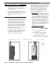
PREINSTALLATION 1. The Infinite Energy boiler is certified for closet installations with zero clearance to combustible construction. In addition, it is design certified for use on combustible floors. 2. Figure 1.1 shows the minimum recommended clearances to allow reasonable access to the boiler for Models IEW-199 and IEW-399. However, local codes or special conditions may require greater clearances.E. D. COMBUSTION AND VENTILATION AIR D. COMBUSTION AND VENTILATION AIR 1.
PREINSTALLATION 4. Indoor Air Opening Size and Location: Openings connecting indoor spaces shall be sized and located as follows: a. Combining Spaces on the Same Floor: Provide two permanent openings communicating with additional spaces that have a minimum free area of 1 in2 per 1000 Btu/hr (22 cm2 per 1000 W) of the total input rating of all gas fired equipment but not less than 100 in2 (645 cm2).
PREINSTALLATION ii. Where communicating with the outdoors through horizontal ducts, each opening shall have a minimum free area of 1 in2 per 2000 Btu/hr (22 cm2 per 2000 W) of total rated input for all appliances in the space, see Figure 1.6. 6. Combination Indoor and Outdoor Combustion Air: If the required volume of indoor air exceeds the available indoor air volume, outdoor air openings or ducts may be used to supplement the available indoor air provided: a.
PREINSTALLATION i. The interlock shall prevent the main burner from igniting if the damper fails to open during burner startup. ii. The interlock shall shut down the burner if the damper closes during burner operation. 10. Combustion Air Ducts: a. Ducts shall be constructed of galvanized steel or an equivalent corrosion-resistant material. b. Ducts shall terminate in an unobstructed space, allowing free movement of combustion air to the appliances. E. PLANNING THE LAYOUT 1.
BOILER SET-UP 2. BOILER SET-UP A. GENERAL B. FLOOR STANDING INSTALLATION 1. Infinite Energy boilers are intended for installation in an area with a floor drain or in a suitable drain pan. Do not install any boiler where leaks or relief valve discharge will cause property damage. 2. The Infinite Energy boiler is not intended to support external piping. All venting and other piping should be supported independently of the boiler. 1.
VENTING & AIR INLET PIPING 3. VENTING & AIR INLET PIPING A. GENERAL WARNING 1. Install the Infinite Energy boiler venting system in accordance with these instructions and with the National Fuel Gas Code, ANSI Z223.1/NFPA 54, CAN/CGA B149, and/or applicable provisions of local building codes. 2. The Infinite Energy boiler is a direct vent appliance and is ETL Listed as a Category IV appliance with Intertek Testing Laboratories, Inc.
VENTING & AIR INLET PIPING d. If the vent pipe and air inlet pipe terminations penetrate the wall at the same level the minimum distance between them is 8" center-to-center. • Provide a minimum of 1 foot (30 cm) distance from any door, operable window, or gravity intake into any building. e. For multiple boiler installations, the minimum horizontal distance between the inlet of one boiler to the exhaust of an adjacent boiler is 8" center-tocenter.
VENTING & AIR INLET PIPING Figure 3.3: Standard Exhaust and Air Inlet Pipe Penetrations Figure 3.5: Optional Stainless Steel Vent Kit Installation Figure 3.4: Offset Exhaust and Air Inlet Terminations Figure 3.
VENTING & AIR INLET PIPING 8. Vertical Venting Configuration: a. Figure 3.7 shows the approved venting configuration for vertical venting using the standard fittings supplied. b. Locate the air intake pipe inlet 12" above the expected snow accumulation on the roof surface or 24" above the roof surface, whichever is greater. c. Locate the end of the exhaust vent pipe a minimum of 12" above the inlet to the air intake pipe. d. Figure 3.
VENTING & AIR INLET PIPING Table 3.3: Equivalent Length of Fittings Fitting Description Equivalent Length Elbow, 90° Short Radius Elbow, 90° Long Radius Elbow, 45° Short Radius Coupling Air Intake Tee Stainless Steel Vent Kit Concentric Vent Kit 5 feet 4 feet 3 feet 0 feet 0 feet 1 foot 3 feet b. The equivalent length can be calculated as follows. Table 3.4: Sample Equivalent Length Calculation Exhaust Straight Length of Pipe 90° Elbows, SR 45° Elbows, SR Conc.
VENTING & AIR INLET PIPING 7. Exhaust and air inlet piping is to be supported separately and should not apply force to the boiler. 8. Penetration openings around the vent pipe and air intake piping are to be fully sealed to prevent exhaust gases from entering building structures. 9. PVC & CPVC Piping: a. Use only solid PVC or CPVC Schedule 40 or 80 pipe for exhaust venting. Cellular core PVC or CPVC is not approved for exhaust vent. b.
WATER PIPING AND CONTROLS 4. WATER PIPING & CONTROLS A. GENERAL 1. Size water supply and return piping in accordance with system requirements. Do not use smaller diameter piping than the boiler connections. 2. If the Infinite Energy boiler is used to replace an existing boiler, make sure that the system piping is thoroughly cleaned and free from debris before installation. 3.
WATER PIPING AND CONTROLS 4. Back Flow Preventer: A back flow preventer (check valve) is required by some jurisdictions to prevent water in the system from backing up into the city water supply. 5. Pressure Relief Valve: The boiler pressure relief valve is shipped separately for field installation. It is extremely important that this is installed on the boiler return pipe (at the rear of the boiler).
WATER PIPING AND CONTROLS d. Table 4.4 provides the flow rate and pressure drop information that corresponds to various system temperature rise values (DT). The pressure drop shown is for the boiler only. If there is significant system pressure drop in the system, this should be included when specifying pumps. Table 4.4: Flow Rate and Pressure Drop for Various System Temperature Rise Values Temperature Rise / Pressure Drop DT (°F) 20 IEW-199 (°C) GPM LPM 11 18.2 Ft IEW-399 m GPM LPM 68.9 17.12 5.
WATER PIPING AND CONTROLS Figure 4.
WATER PIPING AND CONTROLS Figure 4.
WATER PIPING AND CONTROLS Figure 4.
WATER PIPING AND CONTROLS Figure 4.
WATER PIPING AND CONTROLS Figure 4.
WATER PIPING AND CONTROLS Figure 4.
FUEL PIPING 5. FUEL PIPING Table 5.1: Required Fuel Input A. GENERAL 1. All fuel piping to the Infinite Energy boiler is to be in accordance with local codes. In the absence of local regulations refer to the National Fuel Gas Code, ANSI Z223.1/NFPA 54. 2. Size and install fuel piping to provide a supply of gas sufficient to meet the maximum demand of all appliances supplied by the piping. B. FUEL LINE SIZING 1. The required flow rate of gas fuel to the boiler can be determined by the following.
FUEL PIPING k. Fire the boiler and check for fuel gas odor around the gas valve. If an odor is evident check to make sure that the pressure tap fitting is closed. 4. All gas piping must be leak tested prior to placing the boiler in operation. a. If the leak test pressure requirement is higher than 13.5 inches of water column, the boiler must be isolated from the gas supply piping system. b. If the gas valve is exposed to pressure exceeding 13.5 inches of water column, the gas valve must be replaced. 5.
CONDENSATE DRAIN PIPING 6. CONDENSATE DRAIN PIPING A. GENERAL 1. The disposal of all condensate into public sewage systems is to be in accordance with local codes and regulations. In the absence of such codes, follow these instructions. 2. Proper piping and removal of condensation from combustion is critical to the operation of a condensing appliance. Follow these instructions carefully to assure that your Infinite Energy boiler operates correctly. 3.
CONDENSATE DRAIN PIPING 4. Condensate Neutralizer Container: The condensate neutralizer container is an additional transparent container near the front of the boiler. Fill this container with the condensate neutralizer provided. The neutralizer will be consumed during normal operation and should be checked occasionally to determine if additional neutralizer is necessary. Neutralizer is available in 1 lb bags (#3354159) from your RBI Distributor. E. CONDENSATE DRAIN PIPE INSTALLATION 1.
ELECTRICAL CONNECTIONS 7. ELECTRICAL CONNECTIONS A. GENERAL This appliance is to be wired in accordance with local codes and regulations as defined by the Authority having jurisdiction. In the absence of such local codes, the Infinite Energy boiler is to be wired in accordance with the latest edition of the National Electrical Code, ANSI/NFPA 70. B. CUSTOMER CONNECTIONS 1.
ELECTRICAL CONNECTIONS Figure 7.2: Customer Connections 7. Convenience Outlet: The convenience outlet is provided for a condensate pump during operation. It is not switched with the service switch to allow its use during maintenance. 8. Flame Sensor: The flame sensor uses the principal of flame rectification to sense the burner flame. This is located on the right side of the heat exchanger front plate. After ignition, the control also senses flame through the ignition electrode. 9.
ELECTRICAL CONNECTIONS Figure 7.3: Internal Wiring Schematic for IEW-199 & IEW-399 boilers.
BOILER CONTROL: INTERNAL WIRING & OPERATION 8. BOILER CONTROL: INTERNAL WIRING & OPERATION The control provides 3 domestic hot water modes and can be adapted to several different piping schemes. A. CONTROL OVERVIEW The Infinite Energy boiler control is one of the primary safety devices for the boiler. It controls the ignition sequence, temperature limits, pumps and gas flow to the boiler. It also provides many unique features.
BOILER CONTROL: INTERNAL WIRING & OPERATION B. IGNITION SEQUENCE Figure 8.1 shows the ignition sequence for the Infinite Energy boiler control. Table 8.3 describes each step in the sequence in detail. The boiler control provides dual sensing of the flame to maximize the reliability. The control senses the burner flame with both the flame sensor and the ignition electrode.
BOILER CONTROL: INTERNAL WIRING & OPERATION Period Safety On/Off Demand Status User Interface Display A heat demand has no influence in the Safety On/Off period. The Safety On/Off step will continue even if the demand has ended. This step very quickly opens and closes the gas valve relays and determines if the control is operating correctly. A heat demand has no influence in the Pre-Ignition period. Pre-Ignition Once the internal check is complete, the control begins a Pre-Ignition sequence.
BOILER CONTROL: INTERNAL WIRING & OPERATION C. BOILER CONTROL 1. DHW Modes: The Infinite Energy control enables the installer to choose from 3 different domestic hot water (DHW) modes. Table 8.1 provides a brief overview of the available modes. The following are detailed explanations of the DHW modes. Mode 1 – DHW Store with Sensor: In this mode, the control accepts a temperature input from the domestic tank sensor that is included with the boiler.
BOILER CONTROL: INTERNAL WIRING & OPERATION The control will operate the burner at minimum power until the both the supply and return boiler temperature are more than 9°F (5°C) above the freeze protection setpoint. While this function is active the interface panel will display the following: The following chart shows the range and default values for the Service Notification feature. Min. Max.
BOILER CONTROL: INTERNAL WIRING & OPERATION F. STATUS & FAULT HISTORY 1. General: The Infinite Energy boiler control allows the installer to view the status of several key parameters. In addition, it provides details in English about the last 15 Blocking Errors and the last 15 Lockout Faults. The Status and Fault History can be viewed from the Installer Menu. The Installer Menu Structure is shown in Appendix C of this manual.
BOILER CONTROL: INTERNAL WIRING & OPERATION H. MULTIPLE BOILERS 1. Infinite Energy boiler controls can operate together to control up to 16 boilers for one Domestic hot water demand (single or multiple tanks). Only one DHW Tank Sensor is required to provide this operation.
BOILER CONTROL: INTERNAL WIRING & OPERATION • These temperature offset values are used to change the response of individual boilers to the system setpoint. • Re-attach the User Interface Display. • Connect wires from terminals #11 � between all boilers in the cascade system. See Figure 8.9. • Increasing either of these values will cause the system to react more quickly, but may result in frequent cycling. 2. Cascade Operation: a.
BOILER CONTROL: INTERNAL WIRING & OPERATION I. DEFAULTS 1. Factory Defaults – Restore: By pressing the “Select” key while in the “Factory Defaults” screen. All factory settings will be restored on the control. 2. Site Defaults – Save: To save the current settings as “Site Defaults,” press the “Select” key while in the following menu. 3. Site Defaults – Reset: To restore the “Site Defaults,” press the “Select” key while in the following menu.
START-UP PROCEDURE 9. START-UP PROCEDURE A. GENERAL 1. Confirm that all water, gas and electricity are turned off. 2. Verify that the water piping, venting & air intake piping, gas piping, electrical wiring and electrical components are installed in accordance with the manufacturer’s instructions. Be sure that the boiler is installed in accordance with this manual and good engineering practice. 3. Turn on electricity and gas to the boiler B. CHECK WATER PIPING 1.
START-UP PROCEDURE e. If the values in either of these instances falls outside the parameters listed in Table 5.4, turn off the boiler and contact your RBI representative. For best results, the value should be set for the middle of the range (9% for Natural Gas and 10% for LP Gas). f. Be sure to set the System Test mode to Off so that the boiler will modulate correctly in accordance with the load. g.
START-UP PROCEDURE E. LIGHTING & OPERATING PROCEDURES Figure 9.
TROUBLESHOOTING 10. TROUBLESHOOTING A. BLOCKING ERRORS 1. When a Blocking Error occurs the controller will display a message and an “E” error code on the display module. 2. These error messages and several suggested corrective actions are included in Table 10.1. 3. Certain Blocking Errors will, if uncorrected, become Locking Errors as described is Paragraph B. B. LOCKING ERRORS 1. When a Locking Error occurs the controller will display a message and an “A” error code on the display module.
TROUBLESHOOTING Table 10.1: Control Board Blocking Error Codes (automatic reset): “E” CODE Error Display Internal No. Error Description Corrective Action E01 SUPPLY SENSOR NOT CONNECTED 51 Supply sensor not connected. Check harness and sensor. E02 RETURN SENSOR NOT CONNECTED 52 Return sensor not connected. Check harness and sensor. E04 DHW SENSOR NOT CONNECTED 55 DHW sensor not connected.
TROUBLESHOOTING Table 10.2: Control Board Locking Error Codes (manual reset): “A” CODE A01 A02 A03 A04 A05 A09 Error Display IGNITION ERROR FLAME FAILURE OVERHEAT LIMIT OPEN INTERNAL ERROR GAS VALVE RELAY INTERNAL ERROR SAFETY RELAY INTERNAL SOFTWARE ERR RAM ERROR Internal No. Error Description Corrective Action Three consecutive unsuccessful ignition attempts. 1. Watch the igniter through the observation window. 2. If no spark is present, check the spark electrode for the proper 3/16" gap. 3.
TROUBLESHOOTING Table 10.2 (cont’d): Control Board Locking Error Codes (manual reset): “A” CODE Error Display Internal No. Error Description Corrective Action A12 SOFTWARE OUT OF DATE E2PROM OUT OF DATE 10 Contents of e2prom is not up-to-date.
TROUBLESHOOTING c. This will also occur if the wires are not properly connected. C. WARNING ERRORS The Infinite Energy boiler control will display a blinking screen under several conditions. Several of these conditions provide the error information directly on the screen. Table 10.3 shows sensor errors and corresponding corrective actions. d. If there is a short at the DHW sensor terminals and the DHW mode is set to Mode 1, the DHW system will not operate.
MAINTENANCE 11. MAINTENANCE WARNING Product Safety Information Refractory Ceramic Fiber Product This appliance contains materials made from refractory ceramic fibers (RCF). Airborne RCF fibers, when inhaled, have been classified by the International Agency for Research on Cancer (IARC), as a possible carcinogen to humans. After the RCF materials have been exposed to temperatures above 1800°F (982°C), they can change into crystalline silica, which has been classified by the IARC as carcinogenic to humans.
MAINTENANCE A. GENERAL (WITH BOILER IN USE) General boiler observation can be performed by the owner. If any potential problems are found, a qualified installer or service technician/agency must be notified. 1. Remove any combustible materials, gasoline and other flammable liquids and substances that generate flammable vapors from the area where the boiler is contained. 2. Observe general boiler conditions (unusual noises, vibrations, etc.) 3.
MAINTENANCE 2. Before re-starting the Infinite Energy boiler follow the steps below: a. Reconnect the thermostat wires. b. Open the manual gas shutoff valve and reset the thermostats. c. Observe the boiler function to make sure you see a condensate flow. d. If you do not observe a condensate flow, repeat the above procedure. 3. If the problem is not corrected at this point, it is possible that there is a material deposit problem.
BOILER DIMENSIONS & RATINGS 12. BOILER DIMENSIONS & RATINGS Figure 12.1: Dimensional Drawing Table 12.
BOILER DIMENSIONS & RATINGS Table 12.3: Combustion Air Fan Speeds SERIES INFINITE ENERGY COMBUSTION AIR FAN SPEEDS Fan Speed Boiler Model Input Rate Low Power Ignition High Power IEW-199 199 MBH 1350 3250 5940 IEW-399 399 MBH 1710 3250 7740 Table 12.
REPAIR PARTS 13. REPAIR PARTS Repair parts are available from your local RBI distributor. Note: Remember to include the boiler model number and serial number when ordering parts. Figure 13.
REPAIR PARTS Table 13.1: General Repair Parts – IEW-199 & IEW-399 Description 1 2 3 4 5 6 7 Panel, Jacket Front Door, with Ball Studs Lens for Jacket Front Door Display Module, Argus 852RC Gasket for Display Bracket Bracket for Display Module Hex Nut, #6-32 with Lockwasher Screw, #6-32 x 1/2" LG Phillips Head 8 Flexible Gas Line 3/4" 9 10 11 12 Gasket for Gas Line Manual Shut-off Valve, 3/4" NPT Screw, #10 x 1/2" LG Hex. Hd.
REPAIR PARTS Figure 13.
REPAIR PARTS Table 13.2: Heat Exchanger/Burner Assembly Repair Parts Description Quantity Required (199) Quantity Required (399) Stock Code 1 Ignitor, with Gasket 1 1 3354246 2 Sensor, with Gasket 1 1 3354247 3 Screw, M4 x 8 mm 4 4 — 4 Screw, M5.5 x 14 mm, Fine Thread (0.
APPENDIX A. STATUS SCREENS APPENDIX A.
APPENDIX A.
APPENDIX A.
APPENDIX B. USER MENU APPENDIX B.
APPENDIX B.
APPENDIX C. INSTALLER MENU APPENDIX C.
APPENDIX C.
APPENDIX C.
APPENDIX C.
APPENDIX D. 852-1 INTERFACE ADAPTER APPENDIX D. 852-1 INTERFACE ADAPTER A. OVERVIEW The 852-1 Interface Adapter is designed to allow for electronic interface between the Infinite Energy main control and other electronic devices. 1. Alarm Output: In the event of a blocking or locking error, the 852-1 Interface adapter will provide a contact closure to signal an external device (alarm bell, phone dialer, etc.) of a problem.
APPENDIX D. 852-1 INTERFACE ADAPTER Figure 2: Electrical Wiring E. OPERATION – ALARM CONTACTS Alarm Output: a. The alarm output is a normally open dry contact. If an error is sensed in one of the attached boilers, the Alarm Output contact closes. b. This output can be used with either line voltage or 24 volts to power a lamp, buzzer, phone dialer or building management system. F.
APPENDIX D. 852-1 INTERFACE ADAPTER G. OPERATION – MODBUS INTERFACE 1.
APPENDIX D.
APPENDIX D. 852-1 INTERFACE ADAPTER Table 5 Determination of General Control Status Control Status STATE Value ERROR_NUMBER Value Control is not Communicating Properly 0x00 0x00 Control is Operating Correctly with No Errors Not 0x00 0xFF Control is Operating Correctly with Errors Not 0x00 Not 0xFF Table 6 describes the ERROR_NUMBER values for Lockout Errors. These are errors that require a manual reset to continue boiler operation. Table 7 describes the ERROR_NUMBER values for Blocking Errors.
APPENDIX D.
APPENDIX D. 852-1 INTERFACE ADAPTER Table 8 Modbus Holding Registers (Read/Write) Item Index Address & Holding Registers Parameter Name Range Start 0x0000 Range Start 0x0001 R/W control 0x001A 0x001B R/W control 0x001A 0x001B 14 NOT USED 0x001E 0x001F 15 DHW_SETPOINT 0x001E 0x001F Word byte 10 High byte 10 10 Low byte 11 14 High byte 14 Low byte 3.
APPENDIX D. COMBUSTION TEST RECORD APPENDIX E. COMBUSTION TEST RECORD Infinite Energy Combustion Test Record Contact: Company Name: Address: Phone Number: Fax Number: Email Address: Jobsite Data Job Name: Jobsite Address: Boiler Data Boiler Model: Boiler Serial No.: Manufacture Date: Startup Date: Gas Pressure Static Inlet Gas Pressure (in. w.c.) [With Boiler Off]: Flame Signal High Fire (µA): CO² High Fire (%): Inlet Gas Pressure Drop After Boiler Startup (in. w.c.
WARRANTY LIMITED CONDENSING WATER HEATER WARRANTY WHAT DOES THIS LIMITED WARRANTY COVER? This limited warranty covers the Heat Exchanger for leakage, thermal shock or other malfunction caused by defects in materials and/or workmanship. It extends to the first buyer and to any subsequent owner(s) as long as the water heater remains installed at its original place of installation. FIVE YEARS OF COVERAGE! Model number and serial number are found on the rating plate affixed to the water heater.
260 North Elm Street Westfield, MA 01085 Tel: (413) 568-9571 Fax: (413) 568-9613 7555 Tranmere Drive Mississauga, ONT. L5S IL4 Canada Tel: (905) 670-5888 Fax: (905) 670-5782 www.rbiwaterheaters.com Copyright 2011 Mestek, Inc.