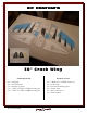
30” Crack Wing By RC Factory Specifications Wing span – 30” / Length – 14” AUW 90 - 100g 2000-2800kV outrunner motor (11g – 18g) 6 - 12 amp ESC / 2s 180 – 250mAh battery 4 ch radio with Elevon Mixing 2x 4g to7g servos / 6x3 to 7x3.5 prop USA Distributor Twisted Hobbys www.twistedhobbys.com Rev: 2013.02.02.
TABLE OF CONTENTS Page WARNING INFORMATION...................................................................................................................................................3 SHIPPING DAMAGE...............................................................................................................................................................3 OUR MISSION .....................................................................................................................................
TWISTED HOBBYS Website: www.twistedhobbys.com – email: sales@twistedhobbys.com Thank you for your purchasing a Twisted Hobbys’ model. Please read through the entire manual before beginning to build this model. If you have any questions please contact us at the above indicated email address. WARNING INFORMATION This R/C Aircraft is not a toy! Read and understand the entire manual before assembly. If misused, it can cause serious bodily harm and property damage.
SAFETY NOTES Before assembling and flying this model, read carefully any instructions and warnings of other manufacturers for all the products you installed or used on your model, especially radio equipment and power source. Check thoroughly before ever flight that the airplanes’ components are in good shape and functioning properly. If you find a fault do not fly the model until you have corrected the problem. Radio interference caused by unknown sources can occur at any time without notice.
kit contents 30” Crack Wing standard parts list: 2x 2x 1x 1x 1x – – – – – wing half side fin/rudder fuselage (3 parts) 1.5mm x 7.0mm x 290mm wing spar 1.5mm x 7.0mm x 600mm wing spar Rev: 2013.02.02.v001b hardware packet: 2x 2x 2x 2x 2x 1x – – – – – – 1.
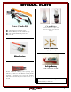
OPTIONAL PARTS Power Combo Kit (Matched by Twisted Hobbys) 1x – 1x – 1x – 1x – 12g Crack Series 2650 kV motor Twisted Hobbys 6A ESC w/dbl bec chip 4.
Tools & Adhesives Needed • Tape Measure and Ruler • Lighter • Small drill bits • Welders Glue • Hobby Knife w/new Blade Blade • Needle Nose Pliers • Wire Cutters • Low Temp Hot Glue Gun • Course Sand Paper • Scissors • Small Phillips Screw Driver • CA and Activator • Approx 18” string/thread Rev: 2013.02.02.
THE BUILD CONSTRUCTION METHODS: Building surface should be at least 2ft x 4ft and flat. Weights or some small heavy objects will be handy for holding things in place during the time glue is setting. Welders glue is used exclusively for this build, except for the control rod ends, which are glued with thin CA. When using using the Welders glue, apply a thin film to each surface, surface, allow to sit for approx five minutes minutes and then assemble. assemble.
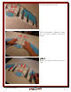
Carefully align the spar slots. While maintaining alignment, bring the two halves together and press firmly. STEP 2 Remove the support tabs from the spar slots. Rev: 2013.02.02.
Locate the wing spars, check their fit into the slots. Coat both sides of the short spar with a bead of Welders. Insert the spar into the forward slot, spreading it a little as you go to help the glue get all the way in. Rev: 2013.02.02.
Coat both sides of the long spar with a bead of Welders. Insert the spar into the rearward slot, spreading it a little as you go to help the glue get all the way in. Press the foam against the spar to secure the bond. Rev: 2013.02.02.
Wipe off any extra glue from both sides Use some tape (high tack tape shown) or other means to maintain pressure on the glue joint while it cures Add some weights to hold everything flat while the glue dries. Rev: 2013.02.02.
STEP 3 Locate the wood control horns. Complete the pre-made slot in the Elevon so that it extends all the way through Test fit the horn. Rev: 2013.02.02.
Coat both sides of the horn with Welders. Lay a small bead of Welders into the slot. Install the horn into the Elevon, make special note to line up the profile of the horn with the profile of the hinge slot as shown. Rev: 2013.02.02.
Wipe off any excess glue. Repeat for the other Elevon. Let everything dry. Apply weights to help keep things flat. STEP 4 Locate the items shown. Rev: 2013.02.02.
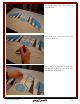
Slide the z-bend and shrink tubing onto one of the carbon push rods Heat shrink the very end only. Apply a few drops of CA down the open end of the heat shrink tubing. Rev: 2013.02.02.
Shrink the tube completely. Apply heat carefully and blot away any CA that is forced out, onto a paper towel. If the glue catches fire remove the lighter and blow out. Repeat for the other control rod. PREPARE THE ELECTRONICS If your motor did not come with 2mm bullets,, add them now. Also note that your power combo may have come with a different motor, same instructions apply. apply. As an option: option you can solder the motor leads directly to the ESC.
Shrink the tubing. Motor ready to connect to the ESC Set up a new program on your Radio, in this case the model has been named “Cwing02” Rev: 2013.02.02.
Go to your System Setup Page. Go to the menu for Wing Type selection. Pick “Elevon” for the Wing Type Rev: 2013.02.02.
Bind your Radio to the Receiver, center all trims, set up the proper direction and controls for the Elevons, set sub trims so servos arms are 90 degrees to the servo and determine correct motor rotation. NOTE: if you chose to solder your motor wires to the ESC you can change the motor direction via the transmitter programming method. Attach the quick link to the Servo arms.
PREPARE SERVOS Add thin (skim) layer of Welders to the three sides of the Servos that come into contact with the surfaces of the cutouts in the wing. NOTE: The method being described will allow for removal of the servos yet hold them tight otherwise. Set the servos aside to allow the skim coating of Welder to dry thoroughly, you should allow a couple hours for this, longer if possible. Put a small bead of Welders on the matching surfaces of the wing cutouts. Rev: 2013.02.02.
Smooth the glue out to a thin coat and allow to dry a couple hours, longer if possible. NOTE: Once the glue has dried, there will still be a “sticky” surface between the servos and wing cut out, hold them securely in place, but still remove-able if needed STEP 5 Locate the lower fuselage doubler Position it as shown. The back edge but be flush with the cutout in the wing.
Trace the location of the doubler Coat each surface with a thin coat of Welders Allow the glue to tack up. Rev: 2013.02.02.
Bring the two piece together, remembering to keep the back edges flush. Completed assembly. If the glue on the servos and wing has dried, you can now install them into the wing cutouts. Servo horns should be sticking out on the bottom side. NOTE: Install these in the same positions as when you did your initial radio setup earlier in the build. Rev: 2013.02.02.
Both Servos in position Decide what batteries you will be using. Mark as required for the foam that needs to be removed. Rev: 2013.02.02.
Remove the material as marked and test fit the battery STEP 6 Locate the upper and lower center ribs. Test fit the upper rib, making sure that the back edge lines up with the cut out in the wing. Rev: 2013.02.02.
Test fit the lower rear rib. NOTE: This part is NOT symmetrical make sure it is orientation is such that the back edge lines up with the cut out in the wing. Glue all the pieces together (wet) and secure with pins or tap. Allow to dry. Locate the motor mount Rev: 2013.02.02.
With the edge of a file or coarse sand paper, rough up one side of the motor mount Roughed up and ready for glue. Coat the roughed up side with Welders, and allow to tack up Rev: 2013.02.02.
Coat the mating surface for the motor mount on the fuselage with Welders, and allow to tack up. Once the glue has tacked up, assemble the two pieces. Motor mount installed and ready for the motor to be installed. Rev: 2013.02.02.
STEP 7 Locate the push rods that assembled with ends earlier were Install the z-bend end into the Elevon Horn. With the Elevon in it’s neutral position, rough cut the push rod to approx. ¼ inch beyond the quick link. Rev: 2013.02.02.
Push back the Elevon and slide the cut end of the push rod thru the quick link. It may be necessary to cut the rod a little shorter. Lightly tighten the set screw. NOTE: Over tightening will crush the carbon rod and ruin your push rod. Repeat for the other side. Rev: 2013.02.02.
Mount the motor… situate so the cables come out in the area where you want to install the ESC. Note: motor shown may be different than the one included in your power combo. Slit the Side Force Generators in prep for assembly to the Elevon. Do the same for both Rudders. Slit in two places Rev: 2013.02.02.
Test fit noting that the larger surface area is the top of the rudder. Lay down a bead of Welders on both sides of the wing in the area that comes into contact with the rudder. Avoid the area directly around the servo, this will make it easier to remove should it fail. Spread the rudder and slide onto the wing from the back side. Align with the tabs and press together. Make sure that the rudder is 90 degrees to the wing. The glue will tack pretty quickly, but until it does make there are no gaps.
The glue will tack pretty quickly, but until it does, make there are no gaps. Repeat the process for the SFG’s. Test fit. Rev: 2013.02.02.
Apply a small bead of Welders in the are the SFG will contact. Install the squareness. SFG and check for Repeat for the other side. Make note of where the Center of Gravity should be located. C.G. = 13mm back back from front spar Rev: 2013.02.02.
Since the battery is in a fixed position on this plane, you will need to balance by locating the ESC and Receiver appropriately. Move the components around until the plane balances 13mm back from the front spar. Note: CG range on Flying wings is much narrower that on conventional planes, take your time and get this as close as you can to the recommended spot.
Bottom side. For this build we chose to keep all the electronics on the top in order to keep them save during landings. …………….. READY SET GO! ENJOY! Rev: 2013.02.02.
Center of Gravity 13mm 13mm back from Forward Spar Locate the electronics to establish the proper Center of Gravity. CG point is 13mm back from the Forward Spar. For flying wings it is important for the location of the CG to be very accurate the acceptable range is very narrow. Rev: 2013.02.02.
Control Throws 3D / Combat Flight: Max Allowed as determined by Rudder Cut-Outs – SEE PICTURES BELOW 60 to 75% expo Sport: 20 degrees all surfaces 30 to 45% expo Depending on your Radio the Elevon mix / setting may “overdrive” the controls surfaces. It is very important to determine the max travel while the transmitter sticks are in the extreme corners of the Gimble.
PREPRE-FLIGHT & testing Preflight Checks Flight Testing Motor: Should run smoothly at all stick The first flights should be done with the CG at the recommended position, and reduced control rates until comfortable with your handling of the aircraft. As your experience with the aircraft grows experiment with different CG points and control rates. After all flights, check the aircraft over for damage and/or other items that may adversely affect flight performance.
NOTES & s/u Sheet Rev: 2013.02.02.
TIPS AND TRICKS - A good building surface is “drop ceiling” panel from a local hardware store on a nice flat board - use parchment paper between the areas being glued and your work surface - heavy flat objects (like books, batteries, etc.) could be used to hold everything flat - When resetting your radio, start with all the ATV’s or throw volumes at 100%. - Make sure you have set the direction of the servos correctly before attempting to trim for zero position.