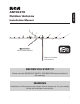
ENGLISH ANT3037X Outdoor Antenna Installation Manual Point Toward Stations Mast not included with antenna. BEFORE YOU START!!! Please read the IMPORTANT SAFETY INFORMATION sheet included in this package. WARNING Installation of this antenna near power lines is dangerous. For your safety, follow the installation instructions.
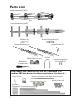
Parts List Back Assembly (VHF) Front Assembly (UHF) Small Flange Nut (6) Washer (6) Corner Reflector (2) Large Screw (2) Mast Clamp Insert U-Bolt Matching Transformer Large Flange Nut for U-Bolt (2) Low Band VHF Add-On Kit For RF Channels 2–6 and/or FM (Not Needed for Most Installations, See Page 3.
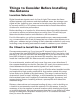
Things to Consider Before Installing the Antenna ENGLISH Location Selection Digital broadcast signals travel via line of sight. That means the fewer objects between your antenna and the broadcast tower, the stronger your signal will be. Installing your antenna in the attic may reduce the signal by as much as 50%, so it is always recommended to install the antenna outdoors for maximum performance.
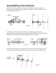
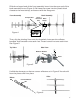
Assembling the Antenna Start by unfolding the VHF elements on the back assembly until the elements are perpendicular to the boom (Figure 1). You should hear the elements click into place. After Before VHF Elements Boom Boom Figure 1 Unfold the six UHF elements on the front assembly until they are perpendicular to the boom. See Figure 2. You should hear the pieces click into place. Pull the two phasing lines away from the boom.
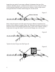
Slide the crimped end of the front assembly boom into the open end of the back assembly boom (Figure 4). Re-insert the screw into the plastic block closest to the mast clamp, and secure with the flange nut. ENGLISH Front Assembly Back Assembly Crimped End Screw Insertion Mast Clamp Site Figure 4 Then, slip the phasing lines onto the threaded rivets near the reflector brackets. Add a washer onto each rivet. Thread a small nut onto each rivet. See Figure 5.
Insert the open end of one corner reflector in-between the top of the reflector brackets (Figure 7). (Elements should be on top.) Align the holes in the brackets with the hole in the corner reflector. Insert a large screw through the holes. Thread a small flange nut on the screw. Figure 7 Reflector Brackets Next, insert the open end of the second corner reflector in-between the bottom of the reflector brackets (Figure 8). (Elements should be on bottom.
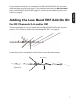
Adding the Low Band VHF Add-On Kit For RF Channels 2–6 and/or FM If unsure whether or not to install the Low Band VHF Add-On Kit, see the section “Do I Need to Install the Low Band VHF Kit?” on page 3. Locate the hole in the bottom of the boom near the mast clamp. Mast Clamp Figure 10 Hole 7 ENGLISH If you determined that you need the Low Band VHF Add-On Kit, proceed with the steps on the next page.
Insert the large screw through the hole in the bottom of the boom (Figure 11). Place the element extension with crimped ends onto the screw. Then, install the clip onto the element extension with crimped ends so that the holes in both parts align. Thread a small flange nut on the screw, and tighten. Figure 11 Large Screw Element Extension with Crimped Ends Place each element extension beside the element to which it will connect.
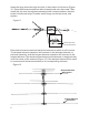
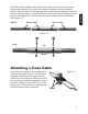
Before Holes to Align Holes to Align Figure 13 After Top Bottom Attaching a Coax Cable Locate the two posts on the underside of the front assembly (Figure 14). Place two washers on each post. Loosely thread a small nut onto each post. Slide one fork of the matching transformer between a set of washers. Repeat for the other fork on the other post. Tighten the nuts, making sure that the forks are still connected. Figure 14 Posts 9 ENGLISH Slide the element sleeve over the element.
Remove the rubber boot from the matching transformer. Slide the rubber boot over the coax cable and install the connector. If your coax cable has the connector already on it, you will need to cut an X in the boot hole so that the boot will slide over the connector. Attach the coax cable to the matching transformer. Then, connect the rubber boot to the body of the matching transformer, as in Figure 15.
Providing Lightning Protection for the Antenna ENGLISH 1. Mount lightning arrestor or 75 ohm grounding block as close as possible to where lead-in enters house. 2. Ground wires for both mast and lead-in should be copper or aluminum wire, number 8 or larger. 3. Lead-in wire from antenna to lightning arrestor or 75 ohm grounding block and mast ground wire should be secured to house with stand-off insulators, spaced from four to six feet apart. 4.
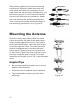
Amplifying the Signal The signal received at the antenna is all the signal the system will ever have; amplifiers can only prevent losing this signal as it runs to one or more televisions. Therefore, mounting location and direction are very important. An amplifier or pre-amplifier may be required if any of the following applies: • The cable between the antenna and the television is longer than 50 feet. • More than one television is connected to the antenna.
Troubleshooting Possible Cause There is static or snow in the picture. Digital television is all or nothing; the picture is crystal clear, or there isn’t one. Static means there is interference between the digital tuner and the television screen. If you use a digital converter, one of the connections or the cable between the converter and television may be bad, or the channel is analog. When using a converter box, make sure the TV set and the output channel of the converter box are on the same channel.
12 Month Limited Warranty VOXX Accessories Corporation (the “Company”) warrants to the original retail purchaser of this product that should this product or any part thereof, under normal use and conditions, be proven defective in material or workmanship within 12 months from the date of original purchase, such defect(s) will be repaired or replaced (at the Company’s option) without charge for parts and repair labor.