RCA COSMAC VIP CDP18S711 Instruction Manual RCA Solid State Division, Somerville, N. J.
ACKNOWLEDGMENT COSMAC VIP has been created by Joe Weisbecker of the RCA Laboratories, Princeton, N.J. so that everyone can have fun and useful personal computer experiences. The elegant and simple hardware system design and the powerful video output together with the customized CHIP-8 language interpreter constitute a fresh and promising approach to personal computers. If questions arise regarding the VIP software or hardware, write to VIP RCA Solid State Division Box 3200 Somerville, N.J.
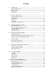
Contents I. Getting Started ...................................................................................................................5 What This Manual Covers .................................................................................................5 The Power Supply ..............................................................................................................6 What You See .....................................................................................................
Contents (Continued) Appendix B - Operating System ................................................................................................. 33 Operating System Listing ................................................................................................. 33 Operating System Register Table .................................................................................... 34 Operating System Summary ........................................................................................
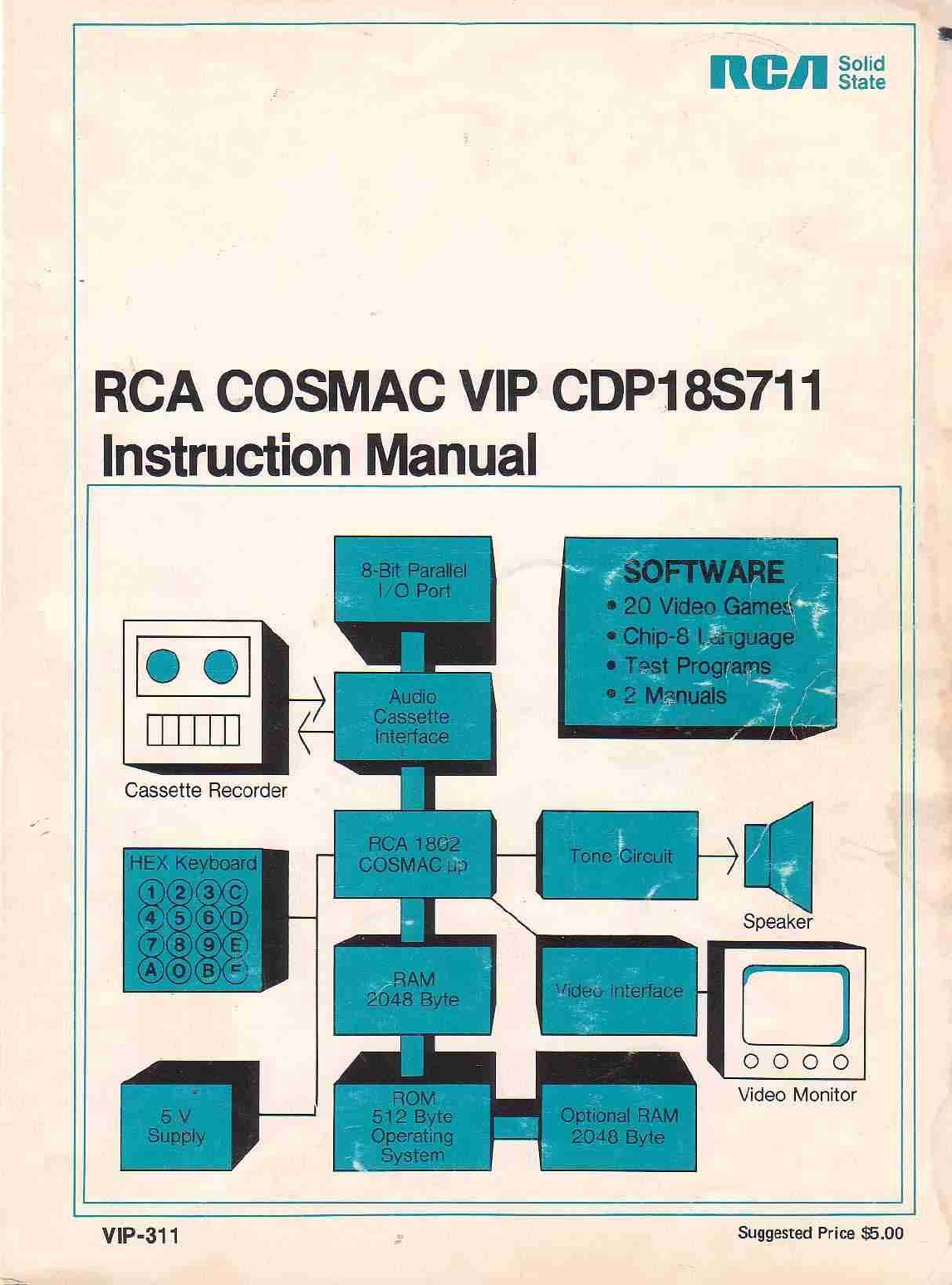
1 1. Getting Started COSMAC VIP (Video Interface Processor) CDP18S711 is a complete computer on a single printed-circuit card.
6 RCA COSMAC VIP Instruction Manual CHIP-8 includes a real time clock, random number generator, decimal conversion, and digit or graphic display capability. It only uses 512 bytes of RAM leaving over 1024 bytes for programs in a 2048-byte system. (You can get an additional 2048 bytes of RAM by plugging four more RAM chips into your card.) With the aid of the User Manual for the CDPI802 COSMAC Microprocessor, MPM-201, you can explore the fascinating world of machine language programming.
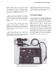
1. Getting Started What You See You must now decide on the video display for your computer. The video pad at the back right comer of the COSMAC VIP card provides a video signal which you can connect directly to the high-impedance input of most standard video monitors. The horizontal sync frequency is 15,720 Hz and the vertical sync frequency is 60 Hz. One solution to your video display need is a commercial video monitor having a suitable input -- not rf or antenna input.
11. COSMAC VIP Operation COSMAC VIP is operated with the RUN switch and hex keyboard. The PWR light shows that power is on. The Q light is activated by various programs. A tone is sounded whenever the Q light is on. The TAPE light glows when cassette input data is present. When using COSMAC VIP, always start with the RUN switch in the down (or reset) position. Flipping the RUN switch up initiates execution of machine language programs beginning at memory location 0000.
contained in the last 256-byte page of the on-card RAM. If you have a 2048-byte RAM, you are seeing locations 0700-7FF on the screen. Bit 7 of the byte at 0700 is in the upper left comer. Try storing a sequence of eight AA bytes followed by eight 55 bytes starting at location 0700. Keep repeating this sequence to draw a checkerboard pattern on the screen. There are 32 rows of spots on the screen. Each row represents 8 memory bytes (64 bits).
. COSMAC VIP Operation 01FF, then load the game program starting at 0200. Record a cassette from 0000 to the end of the game program. When you load this tape, starting at 0000, you will be ready to play the game. Testing Your Cassette System Test your cassette system by entering the beeper program at 0000 (Appendix A). Store 25 at 06FF. Now record 7 pages on a cassette starting at 0000. Load these 7 pages back into memory from the cassette starting at 0000.
III. CHIP-8 Language Programming CHIP-8 is an easy-to-learn programming language that lets you write your own programs. To use the CHIP-8 language, you must first store the 512-byte CHIP-8 language program at memory locations 0000 to 01FF. The CHIP-8 language program is shown in Appendix C in hex form so you can enter it directly in memory using the hex keyboard. You can then record it on a memory cassette for future use. Each CHIP-8 instruction is a two-byte (4-hex-digit) code.
14 RCA COSMAC VIP Instruction Manual Table I - CHIP-8 Instructions Instruction 1MMM BMMM 2MMM 00EE 3XKK 4XKK 5XY0 9XY0 EX9E EXAl 6XKK CXKK 7XKK 8XY0 8XY1 8XY2 8XY4 8XY5 FX07 FX0A FX15 FX18 AMMM FX1E FX29 FX33 FX55 FX65 00E0 DXYN 0MMM Operation Go to 0MMM Go to 0MMM + V0 Do subroutine at 0MMM (must end with 00EE) Return from subroutine Skip next instruction if VX = KK Skip next instruction if VX n.e. KK Skip next instruction if VX = VY Skip next instruction if VX n.e.
III. CHIP-8 Language Programming 15 Fig. 1 - Display screen coordinate structure. pattern for the digit "8" on the screen. First we make up a pattern of bits to form "8" as shown in Fig. 2. pattern will be shown on the screen in the upper left corner. You can write a program to show the "8" pattern on the screen as follows: Fig. 2 - Patternof bitsjorming digit 8. In this example we made the "8" pattern five spots high by four spots wide.
RCA COSMAC VIP Instruction Manual 16 touched any part of a previously displayed pattern. This feature permits programming video games which require knowing if one moving pattern touches or hits another pattern. 0218 021A 021C 021E 0220 0222 0224 0226 0228 022A 022C 022E Because trying to display two I spots at the same position on the screen results in a 0 spot, you can use the DXYN instruction to erase a previously displayed pattern by displaying it a second time in the same position.
111. CHIP-8 Language Programming lose the CHIP-8 interpreter and will have to reload it. You can insert stopping points in your program for debugging purposes. Suppose you want to stop and examine variables when your program reaches the instruction at 0260. Just write a 1260 instruction at location 0260. Flip RUN down and use operating system mode A to examine variables V0-VF. The memory map in Appendix C shows where you can find them.
18 25. RCA COSMAC VIP Instruction Manual PROGRAMMED SPOT - Introduce children to programming concepts by letting them preprogram the movements of a spot or object on the screen. The next section will discuss machine language programming. You can even combine machine language subroutines with CHIP-8 programs if desired.
19 IV. Machine Language Programming VIP Machine Coding For a complete description of machine language instructions, refer to the User Manual for the CDP1802 COSMAC Microprocessor MPM201A.
20 The CHIP-8 language described in the previous section, permits machine language subroutines to be called with a 0MMM instruction. A D4 machine language instruction at the end of the machine language subroutine returns control to the CHIP-8 instruction following the 0MMM instruction. In Appendix C, the CDP1802 register use for the CHIP8 language is provided. R5 is used as the CHIP-8 program counter.
21 V. Logic Description A complete set of logic diagrams is provided in Appendix E. Power requirements for a system with 2048 bytes of RAM is 5 V DC at 350 mA. If you wish to expand the system you can use your own higher current power supply. This system is designed around the CDP1802 microprocessor Wfl. Refer to the CDP1802 data sheet and User Manual for the CDPI802 COSMAC Microprocessor MPM-201A for a complete description of its operation.
RCA COSMAC VIP Instruction Manual pressed. A 62 machine instruction causes the least significant 4 bits of memory byte to be latched into U13. These 4 bits are decoded to bring one of the 16 U13 output lines low. If the key that corresponds to this output line is pressed, the CDPI802 EF3 input will go low. The 4-bit codes latched into U13 correspond to the equivalent key positions.
23 V1. Expansion Considerations and Connections The COSMAC VIP was designed primarily as a self-contained graphic system for home use. Enough RAM and input/output features are provided for years of computer fun without adding anything to your system. If, however, you do want to expand your system, a variety of features have been included to make expansion as easy and inexpensive as possible. You can easily increase RAM to 4096 bytes by adding U20-U23 to your PC card.
24 A single photocell input could be provided via the buffered EF4 line. You can attach the photocell directly between the L and Z pads. Experimentally adjust the pull-up resistor on pad L for best operation. No photocell amplifier should be required to drive the COS/MOS input. An, externally supplied positive pulse- on. Pins 2_and 14 of U25,can be used as an input,byte- strobe when yow want to latch an input byte into U25. A 68 can be used to store this input byte in RAM.
V1. Expansion Considerations and Connections .25 Table III - External Option Terminal Connections (See Fig. E-2, Appendix E) Pin Signal Description Negative-going memory-write pulse Early timing pulse for M address clocking, etc. Memory address lines. High-order address byte appears on these lines during TPA time.
26 RCA COSMAC VIP Instruction Manual Some possible applications for expanded systems include: 1. Counting packages, parts, cars, or people via photocell or switch input. 2. Composing poetry or pictures with printer output. 8. Provide a crystal-controlled, programmable pulse generator, clock, or timer. 9. Provide a programmable sequencer for light shows, advertising displays, holiday lighting, etc. 10. Automatic telephone dialer. 3. Video target games using photocell light gun. 11.
27 VIL Troubleshooting Hints This section is aimed at helping you diagnose and fix hardware problems should they occur. First, check all IC's to make sure they are properly inserted in the PC card. An IC inserted in the wrong direction can be permanently damaged. Check that the +5 V DC supply voltage ripple does not exceed 0.2 volt. Visually inspect the PC card for solder shorts or bad solder joints. Try to avoid zapping your PC card with static electricity charges.
28 up with key C down. With RUN up, check bus and address lines to see if any look different from the others. They will, of course, be at different levels or bouncing around but you might spot something suspicious that would indicate a short or open for one of these lines. Try operating with only a 1024-byte RAM (U16 and U17). Try the other two RAM chips in these sockets. Check U5 inputs and outputs to verify that all stages are inverting properly.
29 Appendix A - Test and Operating Data Byte Pattern for Displaying "COSMAC" The following figure shows how the word "COSMAC" would be formed by spots (or bits) on the display screen. The following bytes when loaded into memory will cause the word "COSMAC" to be shown on the display in a 2048-byte RAM system. Start pattern of bytes at location OFOO in a 4096-byte system.
RCA COSMAC VIP Instruction Manual 30 Cassette Attachment Diagram Cassette Phase Test For best results your cassette recorder should not reverse the phase of an input signal on playback. When playing back a tape recorded on another recorder, it should not reverse the phase of the output signal. You may have to reverse the internal head connections on some cassette recorders to eliminate unwanted phase reversals.
31 Appendix A - Test and Operating Data Cassette Data Test Load the following machine language program into memory: 0000 0008 0010 0018 0020 0028 0030 90 A3 93 10 80 89 17 B6 D3 F6 A7 FE 3A 30 B3 F8 DC F8 DC 23 31 Rewind a blank cassette and put recorder into record mode. Wait 10 seconds and flip RUN up to initiate the program. The byte at location 0033 will be continuously recorded on tape. Flip RUN down to stop recording after a minute or so. You can play this tape to check the signals shown below.
32 RCA COSMAC VIP Instruction Manual Cassette Recording Guidelines 18. When recording give the page key a short tap to start. 1. Use high quality tape (Maxell UD or equivalent). 19. Use the last byte of a tape block as a program identification and check code. It will appear on the display screen after the tape is loaded. 2. Use shortest tapes possible. You can shorten tapes to several minutes in length if you enjoy splicing. 20.
33 Appendix B - Operating System Operating System Listing The following shows the machine language code for the ROM operating system.
34 RCA COSMAC VIP Instruction Manual Operating System Register Table Memory Address 0XB0 0XB1 0XB2 0XB3 0XB4 0XB5 0XB6 0XB7 0XB8 0XB9 0XBA 0XBB 0XBC 0XBD 0XBE 0XBF Register Byte Memory Address Register Byte, R3.0 R4.0 R5.0 R6.0 R7.0 R&0 R9.0 RA.0 RB.0 RC.0 RD.0 RE.0 RF.0 0XC0 0XC1 0XC2 0XC3 0XC4 0XC5 0XC6 0XC7 0XC8 0XC9 0XCA 0XCB 0XCC 0XCD 0XCE 0XCF R3.1 R4.1 R5.1 R6.1 R7.1 R8.1 R9.1 RA.1 RB.1 RC.1 RD.1 RE.1 RF.
35 Appendix C - CHIP-8 Interpreter CHIP-8 Interpreter Listing To use the CHIP-8 language you must first load the following interpreter program into memory 0000 91 0008 A2 0010 B4 0018 FC 0020 45 0028 F9 0030 A6 0038 A7 0040 A3 0048 45 0050 00 0058 01 0060 00 0068 BC 0070 06 0078 F6 0080 FE 0088 0F 0090 87 0098 8E 00A0 AF 00A8 56 00B0 A6 00B8 2D 00C0 5C 00C8 F2 00D0 5C 00D8 B3 00E0 9B 00E8 32 00F0 42 00F8 2A BB F8 F8 A5 AF 50 05 4C D3 30 01 01 7C 91 FA F6 FE AD 32 32 2E 16 93 32 02 32 2C F8 BF DF A
36 CHIP-8 Memory Map RCA COSMAC VIP Instruction Manual CDP1802 Register Use for CHIP-8 Interpreter R0 = DMA pointer (page 0X for display refresh) R1 = INTERRUPT routine program counter R2 = Stack pointer R3 = INTERPRETER subroutine program counter R4 = CALL subroutine program counter R5 = CHIP-8 instruction program counter R6 = VX pointer (R6.1 must not be changed) R7 = VY pointer (available for machine-language subroutines) R8 = Timers (R8.1 = timer, R8.
Appendix C - CHIP-8 Interpreter CHIP-8/Operating System Standard Digit Display Format 37
RCA COSMAC VIP Instruction Manual CHIP-8 User Notes 1 Do not use any of the CDP1802 three-cycle machine language instructions in CHIP-8 programs. 2. CDP1802 R5 is used as the CHIP-8 instruction 5. R7, RC, RD, RE, and RF can be used as working registers in machine language subroutines. Changing other registers can cause the CHIP-8 interpreter to malfunction. counter. It will he addressing the byte following a 0MMM instruction for machine language 6.........................................................
39 A This Appendix contains program listings for twenty video games. These games, which illustrate entertainment applications of COSMAC VIP, were developed by Joe Weisbecker (games, 1 through 8), Joyce Weisbecker (games 9 and 10), Jef Winsor (games 11, 12, and 13), Tom Chen (games 14,15, and 16), and Phil Baltzer (games 17 through 20). In the listing for each game, the first column is the memory location at which the instruction bytes in the second column are stored.
40 RCA COSMAC VIP Instruction Manual 1. VIP Kaleidoscope This program uses the CHIP-8 INTERPRETER at 0000-01FF. Four spots appear in a group at the center of the screen. Press keys 2, 4, 6, or 8 to create a pattern. Keep your pattern smaller than 138 key depressions.
41 Appendix D - Video Games 2. VIP Video Display Drawing Game This program uses the CHIP-8 INTERPRETER at 0000-01FF. A flashing spot appears in the upper left corner of the screen. You can move the spot by holding key 2, 4, 6, or 8. Press key 5 and you can draw a picture with the spot. Press key 0 and the spot can be moved without drawing or used to erase a previously drawn line.
67 Appendix E - Logic Diagrams Fig. E-1 Microprocessor and Display Interface Circuits Fig. E-2 ROM Circuits and Expansion Interface Fig. E-3 Keyboard, Decoding, Audio Oscillator, and Cassette Interface Circuits Fig. E-4 RAM Circuits Fig.
68 RCA COSMAC VIP Instruction Manual Fig.
Appendix E - Logic Diagrams Fig.
70 RCA COSMAC VIP Instruction Manual Fig.
Appendix E - Logic Diagram's 71 Fig.
72 RCA COSMAC VIP Instruction Manuel Fig.
72 RCA COSMAC VIP Instruction Manual Fig.
73 Appendix F Board Layout, Parts List, and Expansion Notes 1. Printed Circuit Board Layout 2.
74 , RCA COSMAC VIP Instruction Manual
Appendix F - Board Layout, Parts List, and Assembly Instructions -76 2. Parts List for RCA COSMAC VIP CDP18S711 Type Number Integrated Circuits - Supplied CDP1802 Ul CDPI 861 U2 SN74L00N U3 SN7474N U4 CD4049 U5 CD4013 U6 CD4011 U7 CD4042 U8 CD4556 U9 CDPR566 U10 CD4051 Ull CD4028 U12 CD4515 U13 CA3401 U14 CA555CE U15 2114 or TMS4045 U16-U19 CD4508 U24,U25 CD4050 U26,U27 Integrated Circuits - Optional 2114 or TMS4045 U20-U23 Qty.
76 RCA COSMAC VIP Instruction Manual 2. Parts List for RCA COSMAC VIP CDP18S711 (Continued) Type Number Qty. Description Resistors - Supplied (1 /4 W except as noted) RI 1 3.3 K ohm R3 R5 RIS Rl6, R33 7 10 K ohm R39, R40 R2, R17 2 1 K ohm R6-RI4 R19, R20 R22-R30, R36 28 22 K ohm R41-R47 R18, R21 2 100 ohm R31, R32 R37, R38 470 ohm R50 R34 1 100 K ohm R35, R49 3 1 megohm R52 R48 1 10 ohm 1/2 W R51 1 4.7 K ohm R4 1 200 ohm Miscellaneous - Supplied I N914 CR1 through 5 Diode CR5 HP5082-4494 3 Red LED 1 3.
Appendix F - Board Layout, Parts List, and Assembly Instructions 77 3. COSMAC VIP Expansion Notes a. Soldering the PC Board In the event you wish to make some changes or add components requiring soldering, you should have some experience building electronic kits. The PC board pads are small and close together requiring extra caution when soldering to avoid shorts or solder bridges. Use a low-heat, small-tipped, grounded soldering iron. Keep it clean. Use small gauge, rosin core 60/40 solder.