
User manual

Graphics contained within this publication are for representation only.
5
Chapter 1: Connections and Setup
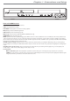
Back of the DVD Recorder
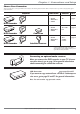
The back of your recorder might look a little overwhelming at fi rst. This section explains what goes where and why. There are two sets of jacks on the back of your unit—
INPUT jacks and OUTPUT jacks.
Each jack is explained individually below, but the basic idea is about sending and receiving information to be played on or through your DVD recorder and displaying that
information on your TV screen.
INPUT The cables connected to INPUT jacks bring the signal INTO the DVD recorder, such as the cable signal (programming) from the cable company or satellite
programming from a satellite receiver.
OUTPUT The cables connected to the OUTPUT jacks are sending the signal from the DVD recorder OUT TO your TV so you can see it on the screen. The correct
cables must be connected to the DVD recorder’s Output jacks and the corresponding Input Jacks on the TV so you can see the program on the TV. You must also tune the
TV to the correct channel, called a Video Input Channel (for details, go to page 18).
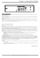
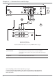
Explanation of Jacks (from left to right)
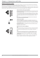
AC-IN – This is where you attach the power cord.
PROG. SCAN switch – If you’ve connected your DVD recorder to a TV that uses progressive scanning to display the image via the Y, Pb, Pr jacks, turn the switch to
the “on” position for progressive scan playback of DVD discs. Typically, only some High Defi nition Televisions and high-end multimedia monitors use progressive scanning.
Leave the switch in the OFF position for S-VIDEO or regular VIDEO (yellow) connections.
Note: If you turn the PROG SCAN switch on, and your TV isn’t capable of progressive scanning you won’t see a clear picture on the TV screen. Additionally, when
playing DVDs you won’t see any picture—press STOP (the main menu appears) and turn the PROG SCAN switch to the OFF position. Try playing the disc again.
INPUT: These jacks receive audio and video from a compatible component, such as a satellite receiver. Another set of Input Jacks (INPUT 2) are on the front of the DVD
recorder for temporarily connecting components such as a camcorder or a video game unit.
VIDEO: Color coded yellow, the video cable you use with this jack provides better quality than an RF Coaxial cable but isn’t as good as S-Video. Connect
corresponding video cable to a compatible component such as a satellite receiver or cable box.
AUDIO L (left): Color coded white, connect corresponding audio cable to a compatible component such as a satellite receiver or cable box.
AUDIO R (right): Color coded red, connect corresponding audio cable to a compatible component such as a satellite receiver or cable box.
COMPONENT VIDEO OUTPUT (Y, Pb, Pr): Some high-end TVs and monitors have Component Video Input jacks. The cables that send the video signal through
these Output Jacks provide the highest resolution because the video signal is divided into 3 separate parts (cables not supplied with DVD recorder). As with VIDEO and
S-VIDEO, COMPONENT VIDEO (Y, Pb, Pr) only carries the picture signal so you need to connect the audio cables so you’ll hear the sound. If your TV has COMPONENT
INPUT jacks, use three video grade cables to connect the DVD recorder to these jacks on the TV to get the best picture quality. However, make sure you also connect
another video cable (either a RF coaxial cable to the CABLE/ANTENNA OUTPUT jack; the yellow cable to the VIDEO Output jack; or an S-Video cable to the
S-VIDEO OUT jack) because you can only use Component Video for DVD Playback.
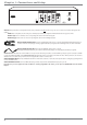
S-VIDEO
IN: If your satellite receiver or cable box has an S-VIDEO output jack, connect the S-Video cable to this jack because it provides better picture quality than standard
video (the yellow jack).
OUT: If your TV has an S-Video jack, connect an S-Video cable to the TV’s S-VIDEO jack and to this S-VIDEO OUT jack on the DVD recorder to achieve better
picture quality than standard video (the yellow jack).
continues on next page…
OPTICAL
ON
OFF
OUTPUT
L
R
PROG.
SCAN
AUDIO
OUT
IN
INPUT
CABLE/ANTENNA
CH4
CH3
AC IN
DIGITAL
AUDIO OUT
COAXIAL
INPUT
S-VIDEO
VIDEO
OUTPUT
Y
Pb
Pr
COMPONENT VIDEO OUT
L
R
AUDIO
VIDEO