User’s Guide 3922 496 30541 August 2007 v5.
LDK 5481 + LDK 4700 User’s Guide ii Declaration of Conformity We, Grass Valley Nederland B.V., Kapittelweg 10, 4827 HG Breda, The Netherlands, declare under our sole responsibility that this product is in compliance with the following standards: - EN60950-1 : Safety - EN55103-1: EMC (Emission) - EN55103-2: EMC (Immunity) following the provisions of: a. the Safety Directives 73/23//EEC and 93/68/EEC b.
LDK 5481 + LDK 4700 User’s Guide i Table of contents Chapter 1 – DigiLink system 1.1 1.2 1.3 1.4 1.5 Introduction . . . . . . . . . . . . . . . . . . . . . . . . . . . . . . . . . . . . . . . . . . . . . . . . . . . . . . . . Accessories . . . . . . . . . . . . . . . . . . . . . . . . . . . . . . . . . . . . . . . . . . . . . . . . . . . . . . . . Compatibility . . . . . . . . . . . . . . . . . . . . . . . . . . . . . . . . . . . . . . . . . . . . . . . . . . . . . . . Configurations . . . . . . . . . .
LDK 5481 + LDK 4700 User’s Guide 3.5 DigiLink base unit connectors. . . . . . . . . . . . . . . . . . . . . . . . . . . . . . . . . . . . . . . . . 3.5.1 Setup switches . . . . . . . . . . . . . . . . . . . . . . . . . . . . . . . . . . . . . . . . . . . . . . . 3.5.2 Audio out connector. . . . . . . . . . . . . . . . . . . . . . . . . . . . . . . . . . . . . . . . . . . . 3.5.3 External video input connector . . . . . . . . . . . . . . . . . . . . . . . . . . . . . . . . . . . 3.5.
LDK 5481 + LDK 4700 User’s Guide | DigiLink system 1-1 Chapter 1 DigiLink system 1.1 Introduction The DigiLink system consists of an LDK 5481 camera adapter and an LDK 4700 base unit for use with Grass Valley standard definition (SDTV) camera heads. The system features digital signal processing and digital transmission of all signals between the camera head and base unit to ensure there is no loss of quality.
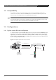
LDK 5481 + LDK 4700 User’s Guide | DigiLink system 1.3 1-2 Compatibility If you wish to control your camera locally, you can connect an OCP 400 to the RS-232 connector of the camera. When an OCP 400 panel is used with the DigiLink system, C2IP functions (e.g. file management) are not supported by the system. ☞ 1.4 Note The LDK 5481 adapter is backwards compatible with existing LDK 5480 breakout boxes and can be connected to them as described in the LDK 5480 User’s Guide. Configurations 1.4.
LDK 5481 + LDK 4700 User’s Guide | DigiLink system 1-3 When a DC power cable is used to power the camera from the base unit, refer to section 3.5.13 for the pin layout of the DC connector. The maximum length of the cable depends on the type of cable and the power used by the camera. The table below is an indication of the cable lengths that can be used. Table 1-2. cable length indication for DC power cable listed cable type ☞ cable cross section max. length (3A/40W) max. length (5A/60W) AWG 20 0.
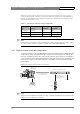
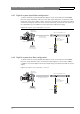
LDK 5481 + LDK 4700 User’s Guide | DigiLink system 1-4 1.4.3 Stand alone SDI coax configuration A camera head with an LDK 5481/00 adapter can be connected to a recorder unit using an SDI coax cable. Only the SDI signal is passed via the coax cable. The maximum length of cable that can be used is 300 m (1000 ft). High quality coax cable should be used (for example, Belden 1694A). The DC power supply for the camera is supplied directly to the adapter. Figure 1-4.
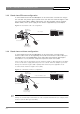
LDK 5481 + LDK 4700 User’s Guide | DigiLink system 1-5 1.4.5 DigiLink system hybrid fiber configuration A camera head with an LDK 5481/20 fiber adapter can be connected to the LDK 4700/20 base unit using a hybrid fiber cable that carries both signal and power. The maximum cable length that can be used is 100 m (330 ft).
LDK 5481 + LDK 4700 User’s Guide | DigiLink system 1.5 1-6 Intercom An intercom channel connects the base unit to the camera operator's headset. The operator's intercom microphone signal is sent to the base unit. The headset can be connected to the 5 pin XLR headset connector at the back of the DigiLink adapter. For the connector and detailed pin descriptions refer to chapter 2.7.7.
LDK 5481 + LDK 4700 User’s Guide | DigiLink Adapter 2-1 Chapter 2 DigiLink Adapter Important information (English) Read this information carefully before installing or servicing this equipment and retain them for future reference. Read and comply with the warning and caution notices that appear in the manual. Any changes or modifications not expressly approved in this manual could void your authority to operate this equipment.
LDK 5481 + LDK 4700 User’s Guide | DigiLink Adapter • 2-2 There are no user servicable parts inside. Refer servicing to qualified personnel only or contact your local Grass Valley representative. Cautions Cautions indicate procedures or practices that should be followed to prevent damage or destruction to equipment or property. • Always switch off the camera before changing the power supply. • Be extremely careful with the connectors between the camera head and the adapter.
LDK 5481 + LDK 4700 User’s Guide | DigiLink Adapter 2-3 Wenn eine Beeinträchtigung des sicheren Betriebs wahrscheinlich ist, muss das Gerät außer Betrieb gesetzt und gegen ungewollten Betrieb gesichert werden. Dann muss der zuständige Kundendienst benachrichtigt werden. Eine Beeinträchtigung der Sicherheit ist zum Beispiel dann wahrscheinlich, wenn das Gerät nicht wie vorgesehen funktioniert oder einen sichtbaren Schaden aufweist.
LDK 5481 + LDK 4700 User’s Guide | DigiLink Adapter 2-4 Fiber optic transmission units CLASS 1 LASER PRODUCT LASER KLASSE 1 PRODUKT A yellow coloured CLASS 1 LASER PRODUCT label is located on top of the fiber optic connector on the rear panel of the adapter. Laser safety statement (Europe) Fiber optic transmission units are classified as a “CLASS 1 Laser Product” according to EN 60825-1, Safety of Laser products.
LDK 5481 + LDK 4700 User’s Guide | DigiLink Adapter 2.1 2-5 Specifications The DigiLink camera adapter is available in two versions: • The LDK 5481/00 version has a 26-pin multicore connector and two SDI coax connectors to connect to an LDK 4700/00 or LDK 4700/10 base unit; • The LDK 5481/20 version has a hybrid fiber connector to connect to the LDK 4700/20 DigiLink fiber adapter. When ordering, you specify the version you require.
LDK 5481 + LDK 4700 User’s Guide | DigiLink Adapter 2.2 2-6 Dimensions Figure 2-1. LDK 5481 DigiLink adapter dimension sketch 2.3 Compatibility Before using the LDK 5481 DigiLink adapter you must ensure that it is compatible with your camera head. Camera heads with software version v13.0 and higher are fully compatible and do not need to be upgraded. Camera heads with software below this version must be updated. Older camera heads with data board no.
LDK 5481 + LDK 4700 User’s Guide | DigiLink Adapter 2.4 2-7 Controls Figure 2-2. LDK 5481 adapter controls 3 2 1 4 DC out LCP CVBS VF 1. Power source selection switch 2. Power on indicator (green) 3. Tally indicators (red) 4. Circuit breaker button (fuse) 2.4.1 Powering the camera The power supply for the camera and the adapter (+12 Vdc) is normally supplied either via the multicore connector or via the DC IN socket.
LDK 5481 + LDK 4700 User’s Guide | DigiLink Adapter 2.5 2-8 Attaching the LDK 5481 adapter to a camera head The LDK 5481 adapter is shorter than a standard adapter. Before attaching the LDK 5481 adapter to a camera, the carrying handle must be re-positioned on the camera head using the mounting bracket supplied with the adapter. To re-position the carrying handle for a short adapter, proceed as follows: ☞ 1. Remove the viewfinder and any other adapter attached to the camera. 2.
LDK 5481 + LDK 4700 User’s Guide | DigiLink Adapter 2.6 2-9 Mounting a script board To attach the optional script board (LDK 6985/21) to the adapter use the special bracket and screws delivered with the script board. To attach the bracket to the adapter, proceed as follows: 1. Unscrew and remove the four screws attaching the viewfinder holder to the top of the adapter. 2. Place the viewfinder holder on top of the script board bracket and align the screw holes. 3.
LDK 5481 + LDK 4700 User’s Guide | DigiLink Adapter 2.7 2-10 Adapter connectors Figure 2-4.
LDK 5481 + LDK 4700 User’s Guide | DigiLink Adapter 2.7.1 SDI video output connector Figure 2-5. SDI video output connector This BNC connector supplies an SDI video output signal (Y/Cr/Cb 4:2:2) that also includes embedded audio, intercom and private data signals. BNC connector: panel view (X8) 2.7.2 SDI video input connector Figure 2-6. SDI video input connector This BNC connector receives an SDI video input from the base unit.
LDK 5481 + LDK 4700 User’s Guide | DigiLink Adapter 2-12 2.7.3 Multicore connector Figure 2-7. Multicore connector A.+ Battery from VTR (+10.7 to +17V) B.- Battery Ground A B 3 5 6 4 9 10 11 15 16 17 21 22 1 2 7 8 12 13 14 19 18 20 24 23 26-pin male; panel view Panel part number: (X6) 3922 040 02571 This multicore connector can be used to connect either a recorder or a base unit (LDK 4700/10).
LDK 5481 + LDK 4700 User’s Guide | DigiLink Adapter 2-13 2.7.4 Hybrid fiber connector Figure 2-8. Hybrid fiber connector A Fiber IN B Fiber OUT B A 4 3 2 1. 2. 3. 4. Power GND Power GND sense Power + sense Poweer + 1 Neutrik OpticalCon® Hybrid Fiber connector (NO2-4FD-1-R) 2.7.5 Video signal (VF) output connector Figure 2-9. Video signal (VF) output connector This BNC socket provides a 1.0 Vpp analog output video signal. This signal can be assigned in the INSTALL menu of the camera.
LDK 5481 + LDK 4700 User’s Guide | DigiLink Adapter 2-14 2.7.7 Intercom headset connector Figure 2-11. XLR intercom headset connector 1. 2. 3. 4. 5. 1 2 3 Microphone return Microphone Telephone return Telephone left Telephone right Microphone level: -64 dBu / -24 dBu switchable Microphone impedance: >600 Ohm 4 5 Telephone level: +6 dBu nominal Telephone output impedance: <50 Ohm XLR 5-pin female; panel view (X11) 2.7.8 LCP / Fiber power connector Figure 2-12.
LDK 5481 + LDK 4700 User’s Guide | DigiLink Adapter 2-15 2.7.9 DC power output socket Figure 2-13. DC power and tally output connector 1 2 4 3 1. 2. 3. 4. Power ground On air (+5V, 100 Ohm) Housing +12 Vdc (max. 18W) Shield of cable directly to the connector housing. The socket provides access to an internal tally switch. When the camera is on-air, the contact of the internal relay is closed. Hirose 4-pin female; panel view Panel part number: (X3) 2422 026 04675 2.7.
LDK 5481 + LDK 4700 User’s Guide | DigiLink Adapter 2.7.11 Script light power supply socket Figure 2-15. Script light power supply output connector 1. +12 Vdc (maximum dissipation 3W) 2. Power return 3. Shield 1 2 3 Fischer 3-pin female: panel view Panel connector number: (X4) 3922 040 02881 v4.
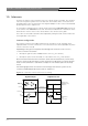
LDK 5481 + LDK 4700 User’s Guide | DigiLink Adapter 2.8 2-17 Install menu The functions shown in the table below appear in the INSTALL menu of the camera head when an LDK 5481 adapter is attached. Refer to the User’s Guide of the camera head for more information on accessing this menu. v4.
LDK 5481 + LDK 4700 User’s Guide | DigiLink Adapter v4.
LDK 5481 + LDK 4700 User’s Guide | Base unit 3-1 Chapter 3 Base unit Important information (English) Read this information carefully before installing this equipment and retain them for future reference. Read and comply with the warning and caution notices that appear in the manual. Any changes or modifications not expressly approved in this manual could void your authority to operate this equipment.
LDK 5481 + LDK 4700 User’s Guide | Base unit 3-2 • Mount equipment so that power lead can be accessed to disconnect power; • Any interruption of the protection conductor inside or outside the apparatus, or disconnection of the protective earth terminal, is likely to make the apparatus dangerous.
LDK 5481 + LDK 4700 User’s Guide | Base unit 3-3 Mit der Montage, Bedienung, Instandhaltung oder Instandsetzung dieser Ausrüstung betrauten Personen wird dringend geraten, sich mit der Theorie und Praxis der Ersten Hilfe vertraut zu machen. Beim Einbau und Betrieb dieser Ausrüstung müssen die örtlichen Gebäudesicherheits- und Brandschutzvorschriften beachtet werden. Vor dem Anschluss der Ausrüstung an die Stromversorgung der Anlage muss überprüft werden, ob der Schutzleiter intakt ist.
LDK 5481 + LDK 4700 User’s Guide | Base unit 3-4 • Um einer Überhitzungsgefahr vorzubeugen, ist das Produkt korrekt zu belüften; • Das Produkt darf nur an eine Stromquelle mit der vorgeschriebenen Nennspannung angeschlossen werden. Fiber optic transmission units CLASS 1 LASER PRODUCT LASER KLASSE 1 PRODUKT A yellow coloured CLASS 1 LASER PRODUCT label is located at the back side of the unit, near the hybrid fiber connector which is at the right side of the back panel.
LDK 5481 + LDK 4700 User’s Guide | Base unit 3-5 • Do not twist the cable when connecting it to equipment. • Insert connectors straight and fully into their corresponding sockets. • In fiber optic cable systems always put the dust caps on cable and panel connectors immediately after disconnecting a cable. Keep the dust caps clean. Installation information Ventilation Cold air is taken in from the right side and expelled on the left side (see drawing).
LDK 5481 + LDK 4700 User’s Guide | Base unit • 3-6 Reliable earthing of rack-mounted equipment should be maintained. Particular attention should be given to supply connections other than direct connections to the branch circuit (e.g. use of power strips). Installation notices For proper installation the following NEC articles should be noticed: Regarding communication circuits: – Installation of equipment (article 800.18).
LDK 5481 + LDK 4700 User’s Guide | Base unit 3-7 according to the wiring rules, shall be provided with a plug in accordance with UNE 20315:1994 For Switzerland Supply cords of equipment having a rated current not exceeding 10A shall be provided vwith a plug complying with SEV 1011 or IEC 884-1 and the following dimension sheet: – SEV 6534-2.
LDK 5481 + LDK 4700 User’s Guide | Base unit 3.
LDK 5481 + LDK 4700 User’s Guide | Base unit 3.2 3-9 Dimensions Figure 3-1. DigiLink base unit dimension sketch 483 mm 465 mm Ready On-air 44 mm 438 mm 255 mm v4.
LDK 5481 + LDK 4700 User’s Guide | Base unit 3.3 3-10 Controls and indicators Figure 3-1. DigiLink base unit controls Ready indicator Display DigiLinK - BASE UNIT Ready LDK 4700 On-air Mains Set-up buttons On-air indicator Power switch and indicator 3.3.1 Powering the base unit Set the power switch to the on position (I). The power on indicator in the switch lights when the unit is powered. 3.3.2 Indicators Table 3-2.
LDK 5481 + LDK 4700 User’s Guide | Base unit 3-11 Press the up or down button to display the required item. Press the select button to select it. The display shows the abbreviation of the current item. Camera Number (CA) When CA is displayed, push the select button to enter the selection mode. Press the up or down button to select an available camera number. Push the select button to set the new camera number. The new camera number is shown in the display.
LDK 5481 + LDK 4700 User’s Guide | Base unit 3.4 3-12 Connecting the studio signalling Connect the studio signalling system to the rear of the base unit. The wiring of the panel connector is shown below. Refer to the next chapter for the location of this connector. Figure 3-4.
LDK 5481 + LDK 4700 User’s Guide | Base unit 3-13 Dry contact signalling Figure 3-6. Dry contact signalling External signaling dry contact base unit signalling connector Voltage level signalling Figure 3-7. Voltage level signalling +5 - 12 Vdc + External signaling with DC output voltage v4.
LDK 5481 + LDK 4700 User’s Guide | Base unit 3.5 3-14 DigiLink base unit connectors Figure 3-2. DigiLink base unit connector locations LDK 4700/00 Camera audio output External/ Reference/ Teleprompter inputs Signalling Intercom Aux. connector Y / Pb / Pr Compontents outputs CVBS outputs (x2) Camera 26-pin multicore Auxiliary Y Audio 1...
LDK 5481 + LDK 4700 User’s Guide | Base unit 3-15 3.5.1 Setup switches The rear of the base unit has six miniature rocker switches. The table below describes their function. Switch them On or Off as follows: Figure 3-8. Dry contact signalling On Off 1 2 34 5 6 Side view of switches Table 3-9.
LDK 5481 + LDK 4700 User’s Guide | Base unit 3-16 3.5.3 External video input connector Figure 3-11. External video input connector Apply a 1Vpp, 75 Ohm video signal to this BNC socket for viewing in the camera viewfinder (or via the VF/ CVBS BNC output socket). BNC connector: panel view 3.5.4 Reference input connector Figure 3-12. Reference signal input connector Apply a 1Vpp, 75 Ohm genlock signal- (C)VBS or Black Burst) - to this BNC socket to synchronize the camera. BNC connector: panel view 3.5.
LDK 5481 + LDK 4700 User’s Guide | Base unit 3-17 3.5.6 Y, Pr, Pb output connectors Figure 3-14. Y, Pr, Pb output connectors These BNC sockets provides 1 Vpp Y, Pr and Pb component video output signals from the camera. These outputs can set to R, G and B with the rocker switch number 2 on the rear of the unit. Off is Y, Pr and Pb; On is R, G and B On Off BNC connector: panel view 1 2 34 5 6 Side view of switches 3.5.7 SDI Camera connectors Figure 3-15. SDI Camera connectors 1.
LDK 5481 + LDK 4700 User’s Guide | Base unit 3-18 3.5.9 SDI video output connectors Figure 3-17. SDI video output connectors These two BNC connectors each supply an SDI video output (Y/Cr/Cb 4:2:2). BNC connector: panel view 3.5.10 RS-232/RS-422 control connector Figure 3-18. RS-232/RS-422 control connector 5 4 9 3 8 2 7 1 6 SubD 9-pin female; panel view (X369) RS-232 (On) or RS-422 (Off) control protocol is selected with rocker switch number 6. On Off 1 2 34 5 6 RS-232 mode RS-422 mode 1. 2.
LDK 5481 + LDK 4700 User’s Guide | Base unit 3-19 3.5.12 Auxiliary connector Figure 3-20. Auxiliary connector 9 8 1 10 7 12 2 11 6 3 4 5 Hirose 12p type HR10A-10R-12SB service part: 2422 026 04355 mating connector: Hirose HR10A-10P-12P 1. 2. 3. 4. 5. 6. 7. 8. 9. 10. 11. 12. RS-232 RXD RS-232 TXD Private data (base unit to camera) GND Private data (camera to base unit) + Batt SDA SCL Housing 3.5.13 DC power output connector Figure 3-21. DC power output connector 1. 2. 3. 4.
LDK 5481 + LDK 4700 User’s Guide | Base unit 3-20 3.5.14 Multicore connector Figure 3-22. Multicore connector 5. Pr: NTSC 700mV 75% saturated colour bar Cr: PAL 525mV (EBU N10) A 5 3 10 17 9 16 2 1 8 15 7 14 21 13 20 24 Cb: PAL 525mV (EBU N10) 4 11 22 6. Pr/Cr Return 7. Pb: NTSC 700mV 75% saturated colour bar B 6 12 19 18 23 26-pin female; panel view Panel part number: T1001017 A.+ Battery from VTR (+10.7 to +17V) B.- Battery Ground 1. 2. 3. 4.