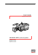
User’s Guide 3922 496 30571 November 2007 v3.
Declaration of Conformity We, Grass Valley Nederland B.V., Kapittelweg 10, 4827 HG Breda, The Netherlands, declare under our sole responsibility that this product is in compliance with the following standards: - EN60950 : Safety - EN55103-1: EMC (Emission) - EN55103-2: EMC (Immunity) following the provisions of: a. the Low Voltage directive 2006/95/EC b.
Table of contents Chapter 1 – Introduction 1.1 1.2 1.3 Technology. . . . . . . . . . . . . . . . . . . . . . . . . . . . . . . . . . . . . . . . . . . . . . . . . . . . . . . . . . 13 1.1.1 HD sensors . . . . . . . . . . . . . . . . . . . . . . . . . . . . . . . . . . . . . . . . . . . . . . . . . . . . 13 1.1.2 Digital processing . . . . . . . . . . . . . . . . . . . . . . . . . . . . . . . . . . . . . . . . . . . . . . . 13 1.1.3 Film-like characteristics . . . . . . . . . . . . . . . . . . . . . . . .
Chapter 5 – Operating instructions 5.1 5.2 5.3 5.4 5.5 5.6 5.7 5.8 5.9 4 Using the camera. . . . . . . . . . . . . . . . . . . . . . . . . . . . . . . . . . . . . . . . . . . . . . . . . . . . . 41 5.1.1 Switching on the power. . . . . . . . . . . . . . . . . . . . . . . . . . . . . . . . . . . . . . . . . . . 41 5.1.2 Controlling the camera. . . . . . . . . . . . . . . . . . . . . . . . . . . . . . . . . . . . . . . . . . . . 41 System Menu . . . . . . . . . . . . . . . . . . . . . . . . . . . .
.10 5.11 User levels . . . . . . . . . . . . . . . . . . . . . . . . . . . . . . . . . . . . . . . . . . . . . . . . . . . . . . . . . . 68 5.10.1 Selecting the user level . . . . . . . . . . . . . . . . . . . . . . . . . . . . . . . . . . . . . . . . . . . 68 Access and Security . . . . . . . . . . . . . . . . . . . . . . . . . . . . . . . . . . . . . . . . . . . . . . . . . . 69 5.11.1 Camera cards . . . . . . . . . . . . . . . . . . . . . . . . . . . . . . . . . . . . . . . . . . . . . . . . . . .
8.2 6 Specifications for LDK 5860 TriaxHD adapter . . . . . . . . . . . . . . . . . . . . . . . . . . . . . 106 8.2.1 Dimensions . . . . . . . . . . . . . . . . . . . . . . . . . . . . . . . . . . . . . . . . . . . . . . . . . . . 107 LDK 8000 HDTV camera system User’s Guide (v3.
End-of-life product recycling Grass Valley’s innovation and excellence in product design also extends to the programs we’ve established to manage the recycling of our products. Grass Valley has developed a comprehensive end-of-life product take back program for recycle or disposal of end-of-life products. Our program meets the requirements of the European Union’s WEEE Directive and in the United States from the Environmental Protection Agency, individual state or local agencies.
Important information Read these instructions carefully and retain them for future reference. During installation and operation of this equipment, local building safety and fire protection standards must be observed. Before connecting the equipment to the power supply of the installation, verify the proper functioning of the protective earth lead. Whenever it is likely that safe operation is impaired, the apparatus must be made inoperative and secured against any unintended operation.
Warnings To prevent fire or shock hazard, do not expose the unit to rain or moisture. If the unit is in a wet or damp environment, a rain cover must be used to protect it for personal safety reasons (EN60065). The rain cover supplied with the unit protects it according to safety specification EN60529 up to level IPX2 (spraying water). To avoid electrical shock, do not remove covers or panels. Refer servicing to qualified personnel only. In case of an emergency ensure that the power is disconnected.
Triax cable systems Only connect a Triax cable from the same LDK camera family to the unit. Do not allow system earth currents to exceed 1.5A in the outer shield of the Triax cable or 0.2A in other cable shields. To avoid excessive earth currents in a Triax system, galvanically separate the power earth connection of equipment connected to the camera from the camera earth. It is strictly prohibited to short circuit the inner and outer shields of a Triax cable used to connect a camera to a base station.
Base Station earthing The rear of the unit has two separate screw terminals for protective earth earth (VE). These are normally connected by a metal strap. (PE) and video VE Metal strap PE The protective earth terminal is internally connected to the protective earth conductor of the power cable. In normal circumstances the connection between the protective earth and the video earth should not be broken.
Precautions To ensure continual high performance from the camera take the following precautions into consideration: • Avoid very damp places. If the environment is wet or damp a rain cover must be used to protect the unit. • Do not subject the unit to severe shocks or vibration. • Do not expose the camera to extremes of temperature. • Do not leave the unit in direct sunlight or close to heating appliances for extended periods. • Do not allow sunlight to shine into the viewfinder.
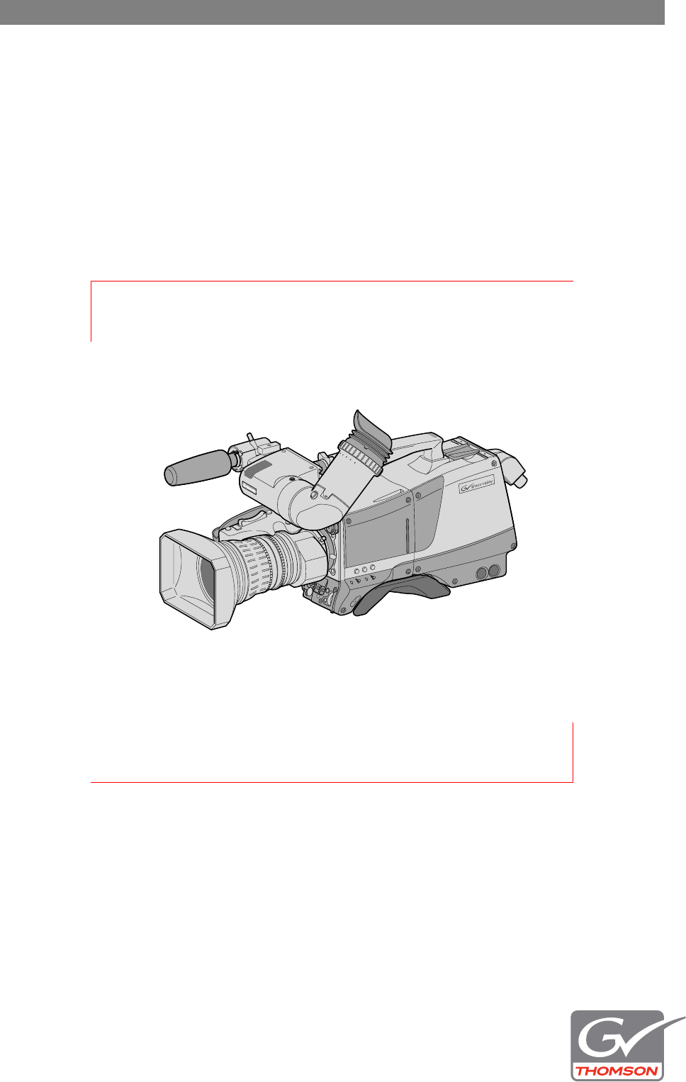
Chapter 1 - Introduction Chapter 1 Introduction 1.1 Technology The LDK 8000 is a high definition multi-standard, multi-format digital camera head using three 2/3-inch HD-DPM+™ sensors. The camera head can be combined with the TriaxHD adapter for a flexible camera that is equally at home in the studio or out on location. The SportCam version can capture true progressive HD images, natively, in multiple formats and frame rates. It supports 2x high-speed acquisition at either 100 Hz or 119.88 Hz. 1.1.
Chapter 1 - Introduction 1.1.3 Film-like characteristics The pivoting knee circuit adapts both the knee point and the compression ratio according to the highlight content of the picture to emulate the softly limiting S-shaped transfer characteristics of film. Digital True Colour Knee circuitry maintains the correct hue for compressed highlights, reproducing colours faithfully, even overexposed skin tones.
Chapter 1 - Introduction 1.1.7 WorldCam version The WorldCam version provides, in addition to the Standard version formats, digital cinematography formats in 1080p and 720p, which give an impression of motion comparable to film cameras running at identical speeds. The WorldCam also provides convenient built-in frame-rate conversions for easy connection to existing HD peripherals, offering possibilities for cost-effective monitoring and recording combined with the motion portrayal of film cameras.
Chapter 1 - Introduction TriaxHD Base Station The TriaxHD Base Station, as well as providing high definition outputs, optionally offers simultaneous high-end SDTV outputs. This facilitates a gradual and managed transition from SDTV to HDTV. TriaxHD high-speed Base Station The SportCam when used together with TriaxHD high-speed Base Station provides a digital dual-phase high-speed output.
Chapter 1 - Introduction • Electronic colour filter can be used for creating a special look (warm/cold) of a scene, or for a smooth colour temperature control around the white balance setting. • Smart card for personal settings and security. • Owner card for setting user levels, and for copying and storing control settings. • Protected, easy-to-operate controls and switches with read-out of all settings. • Viewfinder status read-out of primary camera functions.
Chapter 1 - Introduction 1.
Chapter 2 - Installation Chapter 2 Installation 2.1 Packing/unpacking Inspect the shipping container for evidence of damage immediately after receipt. If the shipping container or cushioning material is damaged, it should be kept until the contents of the shipment have been checked for completeness and the units have been checked mechanically and electrically. The shipping container should be placed upright and opened from the top. Remove the cushioning material and lift out the contents.
Chapter 2 - Installation 2.2 Transport case It is important to protect your camera against damage when transporting it. To do this, a transport case (LDK 5020/00) is optionally available for the camera, lens, viewfinder and some accessories. Figure 2-1. Transport case documentation packing inserts top light tripod plate power supply additional supplies The camera is packed in the transport case as shown in the figure above. This ensures that the camera is not damaged during transport.
Chapter 2 - Installation 2.3 Mounting a lens To attach a lens to the camera head proceed as follows: 1. Ensure that the lens locking ring (1) is in the unlocked position - turned counterclockwise. 2. Remove the dust protection cap (2). 3. Slot the lens into the lens mount (3). 4. Turn the lens locking ring (1) clockwise to lock the lens in place. 5. Connect the lens cable to the lens connector (4) at the right side of the camera. 6.
Chapter 2 - Installation 2.4 2-inch viewfinder 2.4.1 Mounting viewfinder and microphone holder To mount the viewfinder LDK 5302/60 proceed as follows: 1. Loosen locking ring (1) of viewfinder support bracket (2) at the front of the camera handle. (As seen from the rear of the camera, turning the locking ring counterclockwise moves it towards the handle.) 2. Slide the viewfinder onto the viewfinder support bracket. 3.
Chapter 2 - Installation 2.4.2 Positioning the viewfinder The horizontal position of the viewfinder can be adjusted as follows to suit your requirements: 1. Loosen the locking ring (1). (As seen from the rear of the camera, turning the locking ring counterclockwise moves it towards the handle.) 2. Slide the viewfinder horizontally along the rail to the desired position. 3. Tighten the locking ring (1) by turning clockwise. The dioptre hood and eyepiece of the viewfinder can be rotated vertically.
Chapter 2 - Installation 2.5 Viewfinder accessories 2.5.1 Wide angle eyepiece If you regularly use the viewfinder at a distance, for example, when you use the camera in the hand-held position, it is recommended that you fit the optionally available wide angle eyepiece (LDK 5390/00). To fit the wide angle eyepiece proceed as follows: 1. Hold the eyepiece (1) securely. 2. Press the button (2) below the eyepiece tube and swing it free of the button clip (3). 3.
Chapter 2 - Installation 2.6 Mounting a microphone To attach the optional microphone (AJ-MC700) to the camera proceed as follows: 1. Open the microphone holder by unscrewing the knurled screw (2) of the microphone support bracket (1) on the viewfinder and open. 2. Slide the microphone into the split tube until the microphone shoulder reaches the mark (5) in the tube. 3. Place the tube with the microphone into the holder with the split facing upwards. Mount the microphone as straight as possible. 4.
Chapter 2 - Installation 2.7 Tripod adapter plate To mount the camera on a tripod, the tripod plate LDK 5031/10 must first be attached to the tripod. Follow the tripod manufacturer’s instructions to mount the wedge plate supplied with the tripod and the tripod adapter plate firmly onto the tripod. Attach the camera to the tripod adapter plate as follows: 1.
Chapter 2 - Installation 2.8 Adjusting the shoulder pad To change the position the shoulder pad press and hold lever (1). The shoulder pad can now be moved backwards and forwards along the axis of the camera. Adjust the shoulder pad when all units have been mounted to get the best balanced shoulder position. Figure 2-9. Shoulder pad 1 LDK 8000 HDTV camera system User’s Guide (v3.
Chapter 2 - Installation 2.9 Attaching an adapter The camera head is a multi-role camera head that can be used with various adapters. Caution Be extremely careful with the connectors between the camera head and the adapter. Do not allow the guide pins to damage the pins of the connector. Follow these steps in the order given. Tightening or loosening the screws in the wrong order could result in mechanical damage to the camera. To attach an adapter to the camera proceed as follow: 1.
Chapter 3 - Configurations Chapter 3 Configurations 3.1 TriaxHD mode A camera head with the LDK 5860 TriaxHD adapter is connected to a TriaxHD Base Station using a Triax cable. The maximum length of cable that can be used without significant degradation of the video signal is 1,200 m (4,000 ft.) for a 14 mm Triax cable. The power supply is applied to the Base Station and via the Triax cable to the camera.
Chapter 3 - Configurations 3.2 Multiple TriaxHD cameras with C2IP network The Base Stations are each connected to a network hub or router via an Ethernet cable (straight through, not cross-over). The OCP 400 operational control panels and, if required the MCP 400 Master Control Panel, are also connected to the Ethernet network via a hub or router. Figure 3-2.
Chapter 3 - Configurations 3.3 Camera with TriaxHD adapter and SuperXpander A camera head with the LDK 5860 TriaxHD adapter can be mounted in the LDK 4488 SuperXpander (or in the LDK 4489 Xpander). This enables large box lenses to be used with the camera. The LDK 4021 7-inch HDTV viewfinder can be mounted on the SuperXpander. The camera with the TriaxHD adapter connects to the SuperXpander via a flying lead. The power supply for the camera is supplied via this lead.
Chapter 3 - Configurations 3.4 SportCam with high-speed Base Station To obtain a high-speed output, the SportCam must be connected to the high-speed TriaxHD Base Station (LDK 4506). The connection between the SportCam and the Base Station uses the same Triax cable as the other configurations and operational control uses the same C2IP network and units. The high-speed TriaxHD Base Station supplies a dual-phase high-speed HD signal for a recording system. Figure 3-4.
Chapter 3 - Configurations 3.5 Local mode A camera head with the LDK 5860 TriaxHD adapter can be used in the local mode. The DC power supply is applied to the adapter. An OCP 400 operational control panel can be connected directly to the camera using the RS232 connection. A reference signal can be applied to genlock the camera. Standard and WorldCam versions The HD SDI (B) / VF connector at the rear carries the HD SDI viewfinder signal. The HD SDI (A) connector carries the HD SDI camera signal.
Chapter 3 - Configurations 3.6 Triax cable lengths The approximate maximum cable lengths between a Base Station and a camera are given in the table below. The signal degrades gradually when these lengths are exceeded. Reduce these lengths by 20% when a teleprompter signal is sent to the camera. The maximum length is given for cables of the highest quality. The quality of some cables and the interconnections can adversely affect this maximum length. ☞ 34 Cable diameter Maximum length 8 mm (0.
Chapter 4 - Location of controls Chapter 4 Location of controls 4.1 Camera head controls and connectors Figure 4-1. Camera connector location Viewfinder connector Lens connector VF/Mon connector RS232 connector Microphone connector LDK 8000 HDTV camera system User’s Guide (v3.
Chapter 4 - Location of controls Figure 4-2. Camera head controls - front-left Clear Star 4P A 1 Clear ND1/4 B 2 6 ND1/1 C 3 Star 6P 1/64 4 ND us D Soft Foc SW1 SW 2 Std. File Assignable buttons Off Black Str. Col. Temp. Bars r we Po + - Off Gain + - Gain switch Standard file button Black stretch switch Colour temperature switch Power switch Colour bars switch 36 LDK 8000 HDTV camera system User’s Guide (v3.
Chapter 4 - Location of controls Figure 4-3. Camera head controls Zoom control (not on SportCam) Tally indicator Tally indicator Clear Sta r 4P A 1 Clear ND1/4 B 2 ND1/1 C 3 6 1/6 4 ND us D Sof t Foc 4 Sta r 6P Camera card slot Assignable record button White balance switch V-shift switch V VRT star t shift Exp. Tim e Whi te Clean Bal. scan Select Aud io Lev el Audio volume control Exposure time switch Clean scan button Menu select button LDK 8000 HDTV camera system User’s Guide (v3.
Chapter 4 - Location of controls 4.2 TriaxHD adapter controls and connectors Figure 4-4. TriaxHD adapter controls Intercom routing switch Prod Headset production vol. control selection Front Eng Off Prod Rear Progr VF Viewfinder display signal selection Loc Ext1 Mix Ext2 Ext Audio microphone switches Front Rear Mic. Line Eng Call Headset volume controls Mic 1 Call button Line Mic. Ext. SD VF connector output signal selection switch Ext.
Chapter 4 - Location of controls Prod Figure 4-5. TriaxHD adapter connector location Front Eng Off Prod Rear Progr VF Loc Ext1 Mix Ext2 Ext Eng Call Triax connector Front Rear Mic. Line Mic 1 Microphone 1 connector Line Mic. Ext. SD Ext. HD VF +48V Mic 2 Viewfinder out connector VF Microphone 2 connector +48V HD-SDI (B)/VF HD-SDI (B) / VF connector* Intercom headphone connector HD-SDI (A) HD-SDI (A) connector* Power on 12V 1.5A max.
Chapter 4 - Location of controls 4.3 Viewfinder controls and indicators Figure 4-1. Viewfinder controls Tally switch Zebra switch Tally Zebra Crisp Crispening control Option switch Option Contr. Bright. Contrast control Brightness control Figure 4-2. Viewfinder markers and indicators Gain presets - Zoom indicator + ++ Top indicators REC MEDIA BATT ND/RE 45 FOC+ 18 Iris indicator Cadre marker Centre marker Cadre marker Message box Safe area 3.2 4.7 5.6 7.
Chapter 5 - Operating instructions Chapter 5 Operating instructions 5.1 Using the camera Attach lens, viewfinder, microphone and any other accessories to the camera. Attach the triax cable or supply the adapter with power. 5.1.1 Switching on the power ☞ 1. On the Base Station set the master power switch to the on position (I). The green power light lights. 2. Set the camera Power switch of the camera to the on position 3.
Chapter 5 - Operating instructions 5.2 System Menu The camera is operated via the viewfinder text display and the control system menu switches. The systems menu is viewed in the viewfinder and navigated by means of the Rotary control and the Select button which are both located at the front of the camera. Figure 5-1. Menu control buttons V VTR start shift Exp. Time White Clean Bal.
Chapter 5 - Operating instructions Figure 5-2. Main menu Menu off VF Lens Video Install exec MENU: MAIN Files Security Diagnostics Service The MAIN menu screen shows five items. The name of the menu is shown below these. Four more items are hidden but become visible when you scroll down using the Rotary control. A cursor shows your position in the menu. The Rotary control moves the cursor up and down. 5.2.2 Finding your way Use the Rotary control to move the cursor through the menu items.
Chapter 5 - Operating instructions 5.2.3 Leaving the System Menu If you are deep within the menu structure, the recommended way of leaving the System menu is: 1. If necessary move the cursor to the left column with the Select button. 2. Scroll upwards with the Rotary control until the cursor points to TOP (this is the MAIN menu). 3. Press the Select button. The cursor now points to the MENU OFF item of the MAIN menu. 4. Press the Select button to leave the System menu.
Chapter 5 - Operating instructions 5.3 Assigning functions to buttons The camera head has three assignable buttons, two on the side panel (SW1) and (SW2), and one on the lower front panel (VTR start). The operation of the RET and the VTR button on the lens can also be assigned. The function and behaviour (momentary or alternating) of these buttons are set in the INSTALL/BUTTONS menu. 5.3.1 Side panel Location SW1 SW2 SW1 SW2 Std.
Chapter 5 - Operating instructions 5.4 Video acquisition modes In the INSTALL menu choose the video mode you wish to use for acquisition. The tables below show the output signals available for each video mode. 5.4.1 LDK 8000 Standard version Acquisition HD-SDI outputs format (imager) (camera) Viewfinder indication HDTV output (base station) SDTV output (base station) 1080i59.94 Hz A: 1080i59.94 B: VF signal 1080i59 1080i59.94 525i59.
Chapter 5 - Operating instructions 5.4.3 LDK 8000 WorldCam version Acquisition HD-SDI outputs format (imager) (camera) VF menu setting HDTV output (base station) SDTV output (base station) 1080i59.94 Hz A: 1080i59.94 B: VF signal 1080i59 1080i59.94 525i59.94 (NTSC) 1080i at 50 Hz A: 1080i50 B: VF signal 1080i50 1080i50 626i50 (PAL) 1080p23.98 Hz A: 1080psf47.95 B: VF signal 1080psf23 1080psf47.95 colour bar A: 1080psf59.94 B: VF signal 1080i59-23 1080psf59.94 525i59.
Chapter 5 - Operating instructions 5.5 Viewfinder preferences Set up the viewfinder according to your own preferences; adjust viewing parameters, select markers, message boxes and on-screen display times in the VF menu. Figure 5-4. Viewfinder controls Tally switch Zebra switch Tally Zebra Crisp Crispening control Contr. Option switch Option Bright. Contrast control Brightness control 5.5.1 Viewfinder picture quality Adjust the Brightness and Contrast controls according to your preferences.
Chapter 5 - Operating instructions Figure 5-5. Viewfinder markers and indicators Gain presets - Zoom indicator + ++ Top indicators REC MEDIA BATT ND/RE 45 FOC+ 18 Iris indicator Cadre marker Centre marker Cadre marker Message box Safe area 3.2 4.7 5.6 7.5 AWFL AW1 AW2 ! Non-standard Color temperature indicators 5.5.4 Viewfinder markers Go to the VF menu to select the markers you wish to see in the viewfinder.
Chapter 5 - Operating instructions 5.6 Lens preferences When you fit a lens to the camera you may need to adjust the back focus. Refer to the lens manufacturer's instructions to find out how to do this. The LENS menu allows you to choose and, if necessary, adjust other parameters to suit your lens type and your personal preferences. 5.6.1 Lens type In the LENS menu select the lens type from two predefined settings: standard (Std) or wide angle (WA).
Chapter 5 - Operating instructions 5.6.4 Precision focus ☞ Note Set the Lens Interface to digital in the LENS menu before using precision focus. The camera supports the precision focus feature which is offered by some advanced (digital) lenses. This system automatically focuses the image within a user defined focus frame on the screen. When precision focus is enabled on the lens, the focus frame is superimposed on the viewfinder image.
Chapter 5 - Operating instructions 5.7 Video preferences The means used to control the camera depends on your work methods. A remote OCP can be used and a low user level can be selected to restrict the available camera functions. Alternatively, video functions can be controlled on the camera itself.
Chapter 5 - Operating instructions Figure 5-6. Video control buttons Filter wheel switches 1 Clear 2 ND1/4 Star 6P C 3 ND1/16 Soft Focus D 4 ND1/64 r we Po + Col. Temp. Bars Off - Gain + SW 2 - SW1 Std. File Off Black Str. Clear A Star 4P B Standard file button Black stretch switch Colour temperature switch Colour bars switch Gain switch 5.7.2 Test signal The left-front side panel of the camera has a Colour bars switch for switching on a colour bar test signal.
Chapter 5 - Operating instructions Symbol Gain - is always -6 or -3dB 0 is always 0dB + can be set to 3, 6 or 9dB ++ can be set to 6, 9 or 12dB +++ is always 12 dB Variable gain The gain switch can also be used to vary the gain continuously between its minimum and maximum value. 1. Hold the switch continuously in the up or down position until you see the value in the viewfinder change in steps of 0.1dB. 2. Release the switch when you reach the value you want. 3.
Chapter 5 - Operating instructions 5.7.5 Colour temperature selection For true colour reproduction the ambient lighting conditions must be compensated for by selecting a value for the colour temperature. The standard file setting is 3200K (normally used for tungsten and indoor lighting). Two other reference colour temperatures are available: 5600K (for outdoors, clouded conditions) and 7500K (for outdoors, clear blue skies).
Chapter 5 - Operating instructions Variable colour temperature The Colour temperature switch on the left-front side of the camera can also be used to vary the colour temperature continuously between its minimum and maximum value (2500K to 20000K). 1. Hold the switch continuously in the up or down position until you see the value in the viewfinder change in steps of 10. 2. Release the switch when you reach the value you want. 3.
Chapter 5 - Operating instructions ☞ Note If you did not select one of the memory positions FL50, FL60, AW1 or AW2, the ’Precondition fail’ message appears in the viewfinder. 3. Point the camera so that the reference white surface is between the two small white boxes. 4. Press the White balance switch again to start the measurement procedure. A message indicating that the process is runnning appears. - + ++ REC MEDIA BATT ND/RE FOC+ AW2 ! AWHITE: running 3.2 ☞ 4.7 5.6 7.
Chapter 5 - Operating instructions 5.7.6 Exposure time The exposure time values of 1/200, 1/500 and 1/1000 of a second are used to capture fast moving objects so that these can be played back sharply in slow motion. The value selected depends on the speed of the moving object. Figure 5-8. Exposure time controls V-shift switch V VTR start shift Clean scan button Exp. Time White Clean Bal.
Chapter 5 - Operating instructions Lighting The exposure selection also includes lighting control positions which can be used when shooting with lighting that is operating at a different frequency to the camera. There are two positions; 50 Hz and 60 Hz. Each of these positions can be varied further in a range from -10 to +10. To reduce flicker select the frequency closest to the frequency of the lights and then vary the lighting control in the INSTALL menu to obtain the best result.
Chapter 5 - Operating instructions 5.7.8 Reverse scan When the camera is used in a mounted at a rotated angle use the reverse scan feature to digitally rotate the camera’s image to compensate. Go to the INSTALL\REVERSE SCAN menu to switch reverse scan on or off and to select the scan mode (horizontal, vertical or both rotations). 5.7.9 Black stretch The black stretch function changes the level of detail in the shadow areas of the picture without effecting the rest of the picture.
Chapter 5 - Operating instructions 5.8 6. When the process is completed (within a few seconds) the OK message appears in the viewfinder. 7. Adjust the skin detail level with the VIDEO\SKIN\SKIN LEVEL item. Decrease the value below 50 to soften the selected area. Increase the value above 50 to add extra detail.. Controls on the TriaxHD adapter Figure 5-1. Rear controls Intercom routing switch Prod Headset production vol.
Chapter 5 - Operating instructions It is also possible to operate the camera without a Triax cable by supplying a +12 Vdc supply to the DC input socket. The BATT indicator in the viewfinder lights if the camera supply voltage is less than 11V when using an external supply. If excessive current flows in the camera or adapter, the circuit breaker trips and shuts off power to all the units.
Chapter 5 - Operating instructions Figure 5-10. VF output connector signal Front Rear Mic. Line Line Mic. VF output connector signal selection Ext. SD Ext. HD VF VF VF output connector 5.8.3 Using audio Two high quality audio channels are available in the Triax mode. Set the gain levels (-22 to -64 dB) for these channels in the AUDIO section of the INSTALL menu. A high-pass filter for each channel can also be switched on via this menu.
Chapter 5 - Operating instructions Audio channel 2 The channel 2 rear input level switch selects either a line level input or a microphone level input for the channel 2 rear connector (Mic 2). The switch under the Mic 2 socket selects a phantom power supply (48V) for the rear socket. 64 LDK 8000 HDTV camera system User’s Guide (v3.
Chapter 5 - Operating instructions 5.8.4 Intercom Three intercom channels – production (Prod), programme sound (Prog) and engineering (Eng) – are sent from the Base Station to the camera operator's headset. The camera operator's intercom microphone signal is sent to the Base Station. Routing and volume controls for the intercom are on the back of the adapter. Figure 5-12.
Chapter 5 - Operating instructions 5.8.5 Communication Call button Press this momentary button to send a signal to the control panels calling for attention. The ND/RE indicator in the 1.5-inch viewfinder shows when a call signal is sent or received. The call button can also be used to playback a voice mail message that has been recorded in the Base Station. Press once to start playback; press again to stop.
Chapter 5 - Operating instructions 5.9 Managing files You can have access to 15 different files. This number can be extended by using additional scene file camera cards. The Files menu is used to recall and store these files. There are two types of file: • scene files • operator files A scene file contains values related to the picture performance. The operator file contains values related to the set-up of the camera (viewfinder, lens and installation parameters).
Chapter 5 - Operating instructions 5.9.4 Customer standard files You can define a customer standard file for the standard scene file and for the standard operator's file. The contents of the customer files for both these standard files is stored via the SECURITY menu. The selection of a factory defined or a customer defined file for use as a standard file is also made in this menu. You can only access the functions of the SECURITY menu with an owner's card or the PIN code of the camera. 5.
Chapter 5 - Operating instructions 5.11 Access and Security 5.11.1 Camera cards Three camera cards are delivered with each camera. These comprise of two user's cards and one owner's card. Figure 5-13. Camera cards Owner's Card User's Card The owner's card has three functions: • As an access control device to the security settings of the camera. • As a storage device for four scene files. • As a storage device for two operator files. The owner's card is unique to every camera.
Chapter 5 - Operating instructions 5.11.2 Access control The owner’s card or the PIN code is used to access special set-up and security features of the camera. Inserting the owner’s card into the associated camera always gives direct access to the Security menu (PIN code is not required). If you select the Security menu without this card inserted, you must enter the correct PIN code to gain access to this menu. PIN code The PIN code of the camera can be viewed and changed in the Security menu.
Chapter 6 - Menu structure and contents Chapter 6 Menu structure and contents 6.1 Menu structure The structure of the main menus and their submenus are shown on the following pages. The first column shows the user level (0 to 3). You only see menu functions whose user level is equal to or less than the user level set on your camera. Where appropriate, the default value of the function in the standard factory file is shown after the function. 6.1.
Chapter 6 - Menu structure and contents 6.1.2 VF menu structure 2 VF Monitoring Y 0 VF Detail > 0 VF Detail On 0 Focus assist Off 0 Level 50 0 Zebra > 0 Zebra Off 0 Center Cross Off 0 QoS bar Off 0 Iris ind. Off 3 Zebra mode Level 0 Focus Ind. Off 3 Zebra level (%) 90 0 Zoom Ind. Off 3 Zebra contrast 15 0 Box downright Off 0 Safe area Off 0 Safe area type 16:9 0 Marker Off 0 Marker type 4:3 0 Marker style Dot 0 Marker shading Shad 2 Ind. White 70 2 Ind.
Chapter 6 - Menu structure and contents 6.1.3 Lens menu structure 0 Lens type Std 0 AutoIris Off 3 Peak/Average 64 3 AutoIris Setpoint 35 3 Mom.Iris Setpoint 50 0 RE Iris Comp. Off 3 AutoIris Const > 3 Ext.Iris Const > 0 Handgrip Zoom 3 Zoom speed 3 3 3 3 3 AutoIris Gain On S Gain Speed 5 5 S ExpTime Speed 4 Zoom curve 0 3 Min Iris F16 Zoom/Focus Loc 3 Max Iris F2 Lens I/F Analog 3 Min. Exp.Time 1/500 Lens I/F State NotOK 3 Max.
Chapter 6 - Menu structure and contents 6.1.4 Video menu structure 2 Colour Temp > 2 Colour Filter 50 2 Detail > 2 Col.
Chapter 6 - Menu structure and contents 6.1.5 Install menu structure (Triax version) 3 Video mode 3 SideTone Level 50 0 Disable camera Off 1 Cam Mic Swt.
Chapter 6 - Menu structure and contents 6.1.6 File menu structure 2 Store Scenefile > 2 FileSelect 1 Recall Scenefile > 2 Store 1 Store Oper.file > 1 Recall Oper.file > 1 FileSelect 2 Attributes > 1 Recall exec exec 1 FileSelect 1 Store exec 1 FileSelect 1 Recall exec 2 FileSelect 2 Filename 2 Attribute 76 R/W LDK 8000 HDTV camera system User’s Guide (v3.
Chapter 6 - Menu structure and contents 6.1.7 Security menu structure 0 Installed Level User3 0 Cur. User level User3 0 PIN code 0000 0 Customer Files > 0 Green button > 0 Store Cust.Scene exec 0 Cust. Scene attrib. R 0 Store Cust.Oper exec 0 Standard Fact 0 Fact. Filetype Std 0 Scene File Yes 0 Operator File No 6.1.8 Diagnostics menu structure Refer to the next chapter for the menu contents. 6.1.9 Service menu structure Refer to the next chapter for the menu contents.
Chapter 6 - Menu structure and contents 6.2 Menu contents The number (0,1, 2 or 3) in the LEVEL column indicates the user level at which this item is visible in the menu; items with numbers higher than the user level that is set on the camera are not visible in the menu. For example, if user level 2 is set, items marked with a 3 are not visible. ☞ • If an item is not relevant it is not visible in the menu.
Chapter 6 - Menu structure and contents VF menu (user 0) Value(s) Description Level File Iris ind. Off, On Turns the iris indicator in the viewfinder on or off. This indicator shows the F - stop value of the iris opening of the lens. User 0 - Focus ind. Off, On Turns the focus indicator in the viewfinder on or off. This indicator shows the focus distance of the lens: 0 = close-up; 99 = infinity. User 0 - Zoom ind.
Chapter 6 - Menu structure and contents 6.2.2 Lens menu Lens menu (0) Value(s) Description Level File Lens type Std, WA Select a standard (Std) or wide angle (WA) type lens. This settings affects white shading compensation. User 0 Oper AutoIris Off, On Turns auto iris on or off. User 0 - Peak/Average 0..99 (64) Sets the balance between peak and average video level. User 3 Scene AutoIris SetPoint 0..99 (35) Sets auto iris exposure level. User 3 Scene Mom.Iris SetPoint 0..
Chapter 6 - Menu structure and contents 6.2.3 Video menu Video menu (user 2) Value(s) Description Colour temp Level File User 2 Colour Filter 0..99 (50) This electronic colour filter varies the colour balance to obtain warmer or colder effects for the auto-white memory positions. It resets to 50 when the next automatic white balance process is carried out. User 2 - Col. Temp Level 2000..21000 (3200) Shows current variable colour temperature.
Chapter 6 - Menu structure and contents Video menu (user 2) Value(s) Description Level File Width2 Red 0..99 (50) Sets width level for skin gate 2 (red) User 3 Scene Width2 Blue 0..99 (50) Sets width level for skin gate 2 (blue) User 3 Scene Color2 Red 0..99 (50) Sets color level for skin gate 2 (red) User 3 Scene Color2 Blue 0..99 (50) Sets color level for skin gate 2 (blue) User 3 Scene Flare Serv 1 Flare Off, On Turns flare compensation on or off. Serv 1 Scene Red 0..
Chapter 6 - Menu structure and contents Video menu (user 2) Value(s) Description Level File Desat Level 0..99 (50) Sets the desaturation level (when knee mode is Var and Desat is On) Serv 1 Scene Auto Point 0..30 (30) Sets the point where the knee gamma curve begins (when knee mode is Auto). Serv 1 Scene Auto Ref 0..99 (30) Sets the slope of the knee gamma curve (when knee mode is Auto).
Chapter 6 - Menu structure and contents Video menu (user 2) Master Value(s) Description Level File 0..99 (80) Sets the white limiter level. This is the luminance level at which white limiting occurs. Serv 1 Scene Shading White shading Off, On Turns the white shading compensation on or off. Serv 1 - HSawRed 0..99 (50) Sets the horizontal sawtooth value (red). Serv 1 - HSawGreen 0..99 (50) Sets the horizontal sawtooth value (green). Serv 1 - HSawBlue 0..
Chapter 6 - Menu structure and contents 6.2.4 Install menu Install (user 0) Value(s) Description Level File Video mode < available modes > Selects a video acquisition mode (available modes depend on your camera version). User 3 - Disable Camera Off, On Turn disable camera function on or off. User 0 When on, the camera’s user panel is locked. - Intercom User 1 SideTone Level 0..99 (50) Sets the sidetone level (audio feedback to the headphone) in the camera operator’s headphone.
Chapter 6 - Menu structure and contents Install (user 0) Value(s) Description Level File Audio 1 Level -22dB, -28dB, -34dB, -40dB, -46dB, -52dB, -58dB, -64dB Sets input gain level for audio channel 1 (when audio gain mode is set to local). User 1 Oper Audio 1 HPF Off, On Turns high-pass filter for audio channel 1 on or off. Use to reduce 50Hz hum or low frequency noise. User 1 Oper Audio 2 Source Line, Mic, Mic48, Front Selects source for audio channel 2.
Chapter 6 - Menu structure and contents Install (user 0) Value(s) Description Level File Gain ++ (dB) 6dB, 9dB, 12dB Selects gain value for ++ preset. User 2 Oper Gain +++ (dB) 12dB,15dB,18dB Selects gain value for +++ preset. Serv 1 Oper AutoWhite Serv 1 Awb Speed 0..99 (4) Sets the speed for the auto white balance procedure. Serv 1 - Awb Gain 0..99 (10) Sets the gain value for the auto white balance procedure. Serv 1 - Timing User 0 H.Phase 0..
Chapter 6 - Menu structure and contents Install (user 0) Value(s) Description Level File VTR Lens PROD, ENG , Zoom, EXT1, EXT2 Assigns a function to VTR Lens switch: PROD = Production intercom; ENG = Engineering intercom; Zoom = Viewfinder zoom function; EXT1 = switch to external signal 1; EXT2 = switch to external signal 2. User 1 Oper VTR L. Control Mom., Alt. Selects behaviour of VTR Lens switch: momentary or alternating.
Chapter 6 - Menu structure and contents 6.2.5 Files menu Files menu (user 1) Value(s) Description Store scenefile Level File User 2 FileSelect Standard, SCam1..4, SCard1..20, Selects a standard, camera-stored or cardstored scenefile to be restored. User 2 - Store exec Stores the current scene settings in the selected scenefile. User 2 - Recall scenefile User 1 FileSelect Standard, SCam1..4, SCard1..
Chapter 6 - Menu structure and contents 6.2.6 Security menu Security menu (user 0) Value(s) Description Level File Installed level User 0, User 1, User 2, User 3 Selects the user level. User 0 - Cur. user level No Oper, User 0, User 1, User 2, User 3, Serv 1 Displays the current user level. User 0 - PIN Code **** (0000) Enter four digit PIN code to enable access to the Serv 1 level. User 0 - Customer files User 0 Store Cust.
Chapter 6 - Menu structure and contents 6.2.7 Diagnostics menu Diagnostics menu (user 2) Value(s) Description Communication Level File User 2 BS Connected Yes, No Displays base station connection status. User 2 - C2IP Panels 0..99 Displays amount of C2IP control panels connected to the camera. User 2 - DTCP User 3 Packets Recv 0..65535 Displays received packets. User 3 - Packets Sent 0..65535 Displays sent packets. User 3 - Frame Errors 0..65535 Displays frame errors.
Chapter 6 - Menu structure and contents Diagnostics menu (user 2) Value(s) Description Level Board PID Displays Product Identification Code of the selected board. User 2 Board 12NC #### Displays the last 4 digits of the 12NC of the selected board. User 2 Board Status 0..99 Displays the hardware status of the selected board. User 2 BootSw Ver. 0..99 Displays the boot software version of the selected board. User 2 FPGA Ver. 0..99 Displays the FPGA version of the selected board.
Chapter 6 - Menu structure and contents 6.2.8 Service menu Service menu (user 3) Value(s) Description Test Signal Level File User 3 Test Signal Off, On Turns video test signal on or off. User 3 - Test Input DacO, DVP Selects test input. Serv 1 - Test Select SawT, Step Selects test waveform type. User 3 - Test Select SawT, Bars Selects test waveform type.
Chapter 6 - Menu structure and contents 94 LDK 8000 HDTV camera system User’s Guide (v3.
Chapter 7 - Connectors Chapter 7 Connectors 7.1 Camera connectors Figure 7-1. Camera connector location Viewfinder connector Lens connector VF/Mon connector RS232 connector Microphone connector LDK 8000 HDTV camera system User’s Guide (v3.
Chapter 7 - Connectors 7.1.1 Viewfinder connector Figure 7-1. Camera viewfinder connector 1 2 3 4 5 6 7 8 9 10 11 12 13 14 15 16 17 18 19 20 20-pole female; panel view Panel part number: 5322 214 12544 Cable part number (male): 5322 320 12159 1. 2. 3. 4. 5. 6. 7. 8. 9. 10. -80V 1. 2. 3. 4. 5. 6. 7. 8. 9. 10. TDMS Data 2+ n.c. GND INTN-D vf ext video n.c. vf video ret SDA-D SCL-D vf ext video ret 11. 12. 13. 14. 15. 16. 17. 18. 19. 20. GND 11. 12. 13. 14. 15. 16. 17. 18. 19.
Chapter 7 - Connectors 7.1.3 Lens connector Figure 7-3. Camera lens connector 1 9 8 2 10 12 7 11 3 4 6 1. 2. 3. 4. 5. 6. 7. IrisControl 8. 9. 10. 11. 12. + batt * not standard on lens Ext. Video On/Off VTR Trigger Switch -batt Momentary Iris Lens Servo Range Extender Zoom Follow Focus follow* Spare Iris Follow 5 Hirose 12-pole female; panel view Panel part number (X15): 5322 265 10389 Cable part number (male): 5322 265 41208 7.1.4 Audio microphone connector Figure 7-4.
Chapter 7 - Connectors 7.2 Connectors on the TriaxHD adapter Prod Figure 7-2. TriaxHD adapter connector location Front Eng Off Prod Rear Progr VF Loc Ext1 Mix Ext2 Ext Eng Call Triax connector Front Rear Mic. Line Mic 1 Microphone 1 connector Line Mic. Ext. SD Ext. HD VF +48V Mic 2 Viewfinder out connector VF Microphone 2 connector +48V HD-SDI (B)/VF HD-SDI (B) / VF connector* Intercom headphone connector HD-SDI (A) HD-SDI (A) connector* Power on 12V 1.5A max.
Chapter 7 - Connectors 7.2.1 Triax connector Figure 7-6. Triax connector 1. Centre pin: Power and signals 2. Inner shield: Return 3. Outer shield: Camera housing GND Various types of triax connector are available. Outer shield Centre pin Inner shield Panel view (X100) 7.2.2 Viewfinder / External video output connector Figure 7-7. Analogue video output connector This socket provides an analogue1.0 Vpp output viewfinder signal or an external video signal from the Base Station.
Chapter 7 - Connectors 7.2.5 Audio microphone 1 connector Figure 7-10. Audio microphone 1 connector 1. Audio Screen 2. Audio In 3. Audio Return 1 3 2 Microphone impedance > 200 ohm Phantom power +48V switchable Sensitivity range microphone: -64 to -22 dBu Sensitivity range line: +10 to +42 dBu Signal at pin 2 of audio input is in phase with signal at pin 2 of audio output. XLR 3-pole female; panel view (X102) 7.2.6 Audio microphone 2 connector Figure 7-11. Audio microphone 2 connector 1.
Chapter 7 - Connectors 7.2.8 DC power input socket Caution The input voltage must not exceed +17 Vdc. Figure 7-13. DC power input connector 1. 2. 3. 4. 1 2 3 Ground Ground (internally bridged to pin 1) +11.5 Vdc . . . +17 Vdc (internally bridged to pin 4) +11.5 Vdc . . . +17 Vdc This socket accepts a DC voltage of 15V nominal. 4 XLR 4-pin male: panel view (X101) 7.2.9 DC power and tally output socket Figure 7-14.
Chapter 7 - Connectors 7.2.11 Teleprompter output / Reference input connector Figure 7-16. Teleprompter / Reference connector Teleprompter output (Triax mode) This socket supplies the 1.0 Vpp teleprompter signal applied to the Base Station. Reference input (Local mode) BNC connector: panel view (X112) This connector is used to genlock the camera to a 0.6 Vpp HD tri-level reference input signal. 7.2.12 Tracker communications connector Figure 7-17.
Chapter 7 - Connectors 7.2.13 Auxiliary connector Figure 7-18. Auxiliary connector 10 11 9 3 2 8 1 4 5 7 6 Fischer 11-pole female; panel view Panel part number (X109): 3922 040 02512 1. 2. 3. 4. 5. 6. 7. 8. 9. 10. 11. +5VL 0VL AN0 AN1 Spare On-air n.c. Private Data Camera to Base Station Ground Private Data Base Station to Camera Ground Shield Private data input signals: 0 <0.8 Volt; 1 >2.4 Volt max. level: +/-12 Volt input impedance: >100 kOhm baud rate: 2400 bits/s nom; 4800 bits/s max.
Chapter 7 - Connectors 104 LDK 8000 HDTV camera system User’s Guide (v3.
Chapter 8 - Specifications Chapter 8 Specifications 8.1 Specifications for LDK 8000 Item Value Power requirements supplied via adapter or local power Power consumption 60 W (camera head + TriaxHD adapter + viewfinder) Operating temperatures -20 to +45°C (-4 to +113°F) Storage temperatures -20 to +60°C (-4 to +140°F) Weight (approx.) 5.0 kg (11 lbs) incl. 2-inch VF and TriaxHD adapter Pick-up device 3 x 2/3-inch HD-DPM+ CCDs 1080i/720p or 1080p/1080i/720p switchable Picture elements 9.
Chapter 8 - Specifications 8.
Chapter 8 - Specifications 8.2.1 Dimensions Figure 8-1. Dimensions LDK 8000 HDTV camera system User’s Guide (v3.
Chapter 8 - Specifications 108 LDK 8000 HDTV camera system User’s Guide (v3.