Service Manual RCA Model 18V100 Home TV Programmer >~ itc/i l, w Studio II <, Home TV Programmer, Model 18V100 Operation ^ • Testing • Disassembly Parts List
RCA Parts Distributors. Called "Tester I", the cartridge plugs into the slot in the console and checks out the digital circuitry PRODUCT SAFETY NOTICE Studio II uses an isolated power supply to operate the The leakage current to ground of this should be checked at time of game repair. See Page electronic circuitry. in about 30 seconds. See Page 4 for description and Page 15 for ordering information. s> power unit 9 for test procedure.
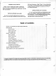
POWER SUPPLY TV/STUDIO 18 FOOT CONSOLE CORD UNIT II SELECTOR SWITCH r r KEYBOARD B KEYBOARD A CHANNEL STUDIO II CONSOLE CLEAR BUTTON ON/OFF INDICATOR LIGHT Figure 1. Studio II 2/CHANNEL 3 SWITCH SOUND ON/OFF SWITCH (UNDER CONSOLE) Major Assemblies Description GENERAL DESCRIPTION Studio for home II console a sophisticated, is microprocessor-based system entertainment using a broadcast TV receiver as the are is on RF oscillator/modulator and audio circuits) PC board.
Studio II Servicing The recommended Studio II service procedure is to determine whether the problem is in one of the periphery components, the interconnecting cables or in the console itself. If the PC board in the console is found to be faulty, it must be returned to RCA for repair on an exchange basis. SELECTOR See Page 14. SWITCH IMPORTANT: No attempt should be made to adjust or repair an inoperative PC board —with the exception of the clock-frequency adjustment described on Page 13.
is indicated on the cartridge sets up TV screen; a test for the if there is no trouble, the two keyboards. NOTE: The Test Cartridge requires substitution of the power unit during test. Use the special 500mA power unit (see Parts List) instead of the original power unit. Press and hold "Clear" button 1. sert Tester on Studio II console. In- cartridge into slot while holding "Clear" button. I Insert cartridge into console with label toward "Clear" button.
!<<>£: sj sj IT laxoos QdVO 3HV0 -M-c+- Figure 10.
satisfactory shifts to the keyboard function), the pattern "OK" black-onpattern of Fig. 9d. The pattern flip-flops between is actuated. white and white-on-black until the "Clear" button normally, the whole sequence If the "Clear" button functions completes the starts again as the button is released. This "Tester I" OPPOSING CAR CONTROLLED BY THE COMPUTER test. the original power unit into the system. Store the special unit with the test NOTE: Reconnect cartridge for future use.
— The keys of Keyboard B "write" on the screen according to the white arrowheads on the keyboard (Fig. 15). To form an interesting pattern, press "Clear" key, then A2, B2 15 times, B6 once, and then BO. The memory stores up to 130 key entries or "moves". After 130 moves, the computer auto' matically starts to repeat the pattern. For 129 or fewer moves. Key BO must be pressed to start the repeat cycle. — Keyboard Tests If "Tester I" cartridge malfunction.
50 ohms resistance with negative ohmmeter polarity on the center conductor. (With positive polarity on center conductor, resistance should be between 20 and 30k ohms.) See "Coaxial Cable Replacement". r test for a substitution with a unavailable, use a new DC result. (Late production units use insulated rivets which eliminate problem)) Power Supply Unit Tests Selector Switch Unit Tests The quickest to the metal box or rivets holding terminal board.
^J Figure 23.
CONSOLE DISASSEMBLY The console 3. halves of the cabinet, printed circuit board, and r a two two keyboards, consists of six separate subassemblies: the Release the keyboard from the console by unlatching two brown colored latches as illustrated. Keyboard now is free of console. "Clear" switch/power-on indicator. The upper and lower halves of the cabinet are separated by removing 5 Phillips-head screws. With the bottom cover removed, the underside of the printed circuit board is exposed.
cable in slot cover (Fig. 27). Shield in minimize radiation of modulated must be fully seated to carrier. 4. From underside of cover, bend clipped pigtails back and collapse black plastic holder with needlenose pliers or diagonal cutters. Remove holder from console holes using pliers or cutter. 5. Install new LED console cover until it holder. Press holder gently into hole in sJ clicks into place (Fig. 29). * Figure 27. Disconnect Co-Ax Shield First to J Replace Cable.
. nected with reversed polarity. Use fabricated tool (Fig. 28) to push LED into holder. LED "clicks" into place. Any tool without a shoulder usually pushes LED out of the holder. r 7. Form snipped leadwires as shown in new LED pigtails to them. Solder quickly heating 8. Fig. 31 and connect to prevent over- LED. Reconnect black, white and yellow leads from PC board to complete installation. CLOCK FREQUENCY ADJUSTMENT PROCEDURE Incorrect clock frequency adjustment causes pattern weave on screen.
PC Board Exchange EXCHANGE PLAN DESCRIPTION RCA operates a PC board refurbishing facility at Swannanoa, North Carolina. Defective PC boards sent to this facility are 5.00* refurbished and returned to the sender at a cost of $1 provided, of course, the exchange board is repairable. PC sure board is filler as shown and pack in carton. check or money order for $15.00*. A refurbished be shipped to the address you supply on the questionnaire packed with defective board. 4.
STUDIO 1 r s C/3 II PC BOARD EXCHANGE QUESTIONNAIRE 1 Please pack completed questionnaire in container with defective board with check or 1 (Price subject to change without notice.) Please describe defect 1 Studio Serial II money order for $15. Nn symptom (s). (Nodisplay, no sound, partial display, 1 < etc.
^ ^ "j 3 Printed RCA | Distributor and Special Products Division Deptford NJ 08096 | Tmk(s) ® Marca(s) Registrada(s) in U.S.A.