THE GRAND PROGRESSIVE SHOTSHELL RELOADING PRESS P R O D U C T I N S T R U C T I O N S
IMPORTANT Before using the RCBS Shot Shell Press, read these instructions carefully to fully learn how to safely operate the related reloading equipment. Failure to properly operate certain reloading equipment can result in severe personal injury and/or equipment damage. If you have any questions while assembling or operating this tool, call us at 1-800-533-5000 or 1-530-533-5191 Monday - Thursday 6:30 a.m. to 3:00 p.m. Pacific Time The instruction manual contains specific safety and operating information.
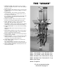
THE “GRAND” 1 POWDER SYSTEM - Hull activated, no hull, no powder. No need to manually turn powder on and off. No spillage of powder can occur. 11 2 SHOT SYSTEM - Hull activated, no hull, no shot. No need to manually turn shot on and off. No spillage of shot when problems occur. 3 CASE HOLDERS - Easy removal of hull at all stations. Universal 12 and 20 gauge case holders allows cases to be sized down around the rim.
UNPACKING THE GRAND A. B. C. D. E. F. Shot Hopper Spent Primer Tube Assembly Powder Hopper Drain Tube (Clear Rubber Hose) Press Assembly Wad Box Video Wad Box Bracket Discharge Chute Primer Tray Bag 1, Parts List #8 x 3/8 Wood Screw 1/4-28 x 1/4 BHCS 3/8 Detent Ball Detent Spring Shotshell Crimp Starter 12 Ga.
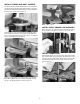
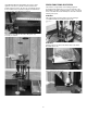
PRESS MOUNTING LOADED ROUND CONTAINMENT Step 1 Attach Discharge Chute to the bottom of the Shell Plate Holder as shown in photo 1. Use two 1/4-28 x 1/4 Button Head Cap Screws and 5/32 hex wrench. For presses mounted directly to the bench, you may want to drill a 3" hole just off the end of the Discharge Chute and catch your loaded rounds beneath the bench. Step 2 Mount your press to a solid bench.
INSTALL POWDER AND SHOT HOPPERS The Powder Hopper (smaller diameter tube) is to be mounted on the left and the Shot Hopper (larger diameter tube) on the right. ➞ Install detent spring then ball into hopper funnel assembly and install on the press as shown in photo 11. 14 Note: In OFF position INSTALL SPENT PRIMER TUBE ASSEMBLY 11 Raise ram to the top of the press stroke and install the tube as shown in photo 15. Tighten the setscrew to secure the tube. Do not over tighten, use 3/32 hex wrench.
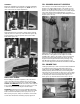
PRESS FUNCTIONS BY STATION Install Wad Box Bracket approximately six inches from the right side of the press to provide clearance between the handle and the box (photo 18). The top of the Bracket should be flush with the bench top. Attach using the two 8x32 Wood Screws provided. Hang Wad Box on Bracket. The Grand is an eight-station auto indexing progressive shotshell reloader. All functions occur on the upstroke of the Ram with the exception of indexing, which occurs on the down stroke of the Ram.
STATION 5 Primer Transfer Bar delivers the primer to the primer station (photo 23). Shot Drop and Wad Seating. Case activated, will not drop a shot charge without a hull with a wad present. Drop Tube (A), driven by the bottom of the wad cup, drives the Shot Shut Off gate (B) to drop the shot charge (photo 26). If no hull is present or a hull with no wad (photo 27), the Drop Tube assembly does not activate the Shot Shut Off gate. The Wad is seated at the top of the stroke.
STATION 7 FILL POWDER AND SHOT HOPPERS Crimp. The Crimp Die is pre-adjusted for Federal Gold Medal Hulls with a Federal 12S3 wad (photo 29). NOTE: The use of other components may require adjustments. The next step is to load the Powder Hopper. The Powder Hopper is the smaller diameter tube on the left. Be sure the Hopper is in the ON (middle) position as shown in photo 32. Remove the cap and pour the powder into the Powder Hopper.
Open the Primer Tray Lid. Place a sleeve of 209 primers upside down on the Primer Tray. Slide the outer sleeve off to the rear. You will need to slightly raise the outer sleeve to clear the Primer Tray Lid. The primers will be properly oriented. Properly close the Primer Tray Lid and replace Primer Tray onto Priming Tube. (Tip: Drop four to five primers manually into the Primer Drop Tube before installing the loaded Primer Tray.
31/2" hulls, remove top lock nut (D) and socket head cap screw on Wad Guide Arm and raise upper half of Wad Guide Arm. Position upper half of Wad Guide Arm to clear the hull and reinstall socket head cap screw and nut. You must also raise the Wad Starter Rod. Due to shot cup length of some 11/4 oz. and greater wads, you may have to manually insert wads. First, remove the Wad Carrier arm and remove the Wad Guide.You then place a wad into the Wad Guide and place over the hull mouth. Cycle the press.
6. Shot Drop and Wad Seating Station Adjustment #5 size shot is the largest size The Grand will dispense. Larger shot sizes must be weighed separately and manually put into the hull prior to the Crimp Start station. Due to varying base wad heights and design, as well as wad design, it may be necessary to adjust the Lower Shot Tube to obtain proper wad seating depth.
(CAUTION: Be sure to support underneath the Charge Bar to keep from dropping the Bushings out the bottom.) Install appropriate Powder and Shot Bushings, the Shot Bushing is the larger diameter of the two and should be on the right side, reinstall the Charge Bar. (NOTE: The windows on the Charge Bar allow you to see what type of bushings that you have installed, the windows should face the front of the press.) Reinstall Charge Bar Locking Pin through the Index Shaft Bracket and Charge Bar.
8. Primers do not drop from Collet to Transfer Bar: Check Collet for damage or burrs. Check Primer Transfer Bar for damage or burrs. Loosen lock nut (B) on the top of the Primer Drop Tube and adjust down in 1/4 turn increments until primers drop freely. Retighten lock nut (photo 47). (CAUTION: Adjusting the Primer Drop Tube Assembly too far down may cause damage to the Primer Transfer Bar.) A ➞ ➞B 47 9.
May be sporadic due to a damaged Case Holder, only affects one of the eight case holder stations. If multiple Case Holders are damaged, it will happen more frequently. Damaged Case Holder(s) need to be replaced. 20. Hard ejection of loaded round at Station 8: Typically caused by a damaged case holder. The Case Holder does not retract causing extra force to be used to eject round. If multiple Case Holders are damaged, it will happen more frequently. Damaged Case Holder(s) need to be replaced.
MAINTENANCE Three areas that require more frequent lube are the Shell Plate Assembly, (photo 1) contact area of the (photo 2) Wad Carrier and the (photo 3) back Support Rod. Any light oil or grease will suffice. The Case Holder Assembly must be removed to properly lubricate. Follow Troubleshooting #20, page 12 for directions on how to properly remove and replace the Shell Plate Holder Assembly.
89100 THE GRAND, Charge Bar POWDER CHARGE WEIGHT IN GRAINS GRAINS 14 15 16 17 18 19 20 21 22 23 24 25 26 27 28 29 30 31 32 33 34 35 36 37 38 39 40 41 42 43 Accurate Solo 1000 Accurate Solo 1250 Accurate No.
THE GRAND PARTS LIST • NOVEMBER 2003 # 1 2 3 4 5 6 7 8 9 10 11 12 13 14 15 16 17 18 19 20 21 22 23 24 25 26 27 28 29 30 31 32 33 34 35 36 37 38 39 40 41 42 43 44 45 46 47 48 49 50 51 52 53 54 55 56 57 58 59 60 61 62 63 64 65 66 67 67 68 69 69 70 71 72 72 73 74 75 76 77 78 Description Part # SS Frame 789000 SS Top Plate 789001 SS Support Rod 789023 SS Support Rod Turned 789031 3/8-16 x 1 Flat Head Cap Screw 188750 Link Pin Left 788258 Link Pin Right 788257 SS Ram 789020 Detent Ball 187152 Detent Spring 18
16
PRECISIONEERED ® RELOADING EQUIPMENT We think that we make the very best reloading equipment in the world. If you agree, please tell your friends. If you disagree, tell us - we want to do something about it! Customer Service 1-800-533-5000 (US or Canada) or 530-533-5191 Hours: Monday - Thursday, 6:30am - 3:00pm (hours may vary) e-mail: rcbs.tech@atk.com • www.rcbs.com RCBS • 605 Oro Dam Blvd.