
User Manual


RCF spa
M 18 Digital Mixer User’s Manual
15
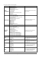
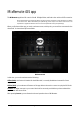
Inputs 01
-
08
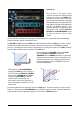
The left part of the center column
contains on the top left a BACK button (1)
to allows you return to the INPUTS view,
followed by the pan control which also
shows fader value in dB when moved (2),
the Mute (3) button, the channel editable
name (4), the fader (5), the PFL (6) button
and the non-editable number of the
hardware input (7). The larger part of this
page shows a rack containing RCF PRE,
RCF GATE and RCF COMPRESSOR, above
the latter two there is a box to recall
presets.
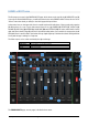
The two large arrow buttons on bottom left and right enable you to change input channel immediately,
without requiring to go back to the INPUTS view.
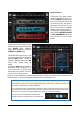
The RCF PRE preamplifier features GAIN (from 0 dB to 60 dB in 10 dB steps), TRIM (from 0 dB to -10 dB in
0.1dB steps), the LED indicating the activation of the Phantom 48V power over the INV switch (phase
inversion). The display shows the values of each parameter, including the frequency of the HPF (selectable
between 10Hz and 500Hz) which is activated via its ON button.
The second unit is the
RCF GATE
, topped by its
Preset
box, with ATTACK and RELEASE time controls,
THRESHOLD level and RANGE intervention, completed by
the display and the activation switch. On the left you can
see the characteristic curve of the internal GATE: when
the input signal goes below the THRESHOLD, its level is
reduced by RANGE dBs.
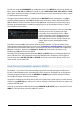
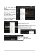
The third unit is the RCF COMPRESSOR,
topped by its Preset box, with a display on
the left, followed by ATTACK and RELEASE
times controls, THRESHOLD level, RATIO
compression, POST GAIN level and the
activation switch. On the right, the
characteristic curve of the compressor is
shown, including the contribution of POST
GAIN control.
For faster adjustments, the compressor features the Easy option, located in a small box on the left of the
Preset box - Easy has only the COMPRESSION control (based on input level signal with preset thresholds,
with automatic Post Gain adjustment) against the five controls of Advanced option.
1
5
3
4
2
6
7
0 dBFS IN
OUT
0 dBFS
THRESHOLD
RANGE
0 dBFS IN
OUT
0 dBFS
THRESHOLD
POST
GAIN