Contents RCOM Pro20 Program Manual ( 1 ) Installation Specifications and CD File Contents 2 ( 2 ) Driver Installing 4 ( 3 ) Rcom Pro20 FONT Installation 8 ( 4 ) Rcom Pro20 System Program Installation 9 ( 5 ) Communication Linkage between Incubator and Computer 11 ( 6 ) How to Incubate Easily with PC 13 ( 7 ) Explanation of Each Part 14 ( 8 ) Start Incubation 21 ( 9 ) Special Mode Setting of Temperature & Humidity 23 (10) Real- time Temperature & Humidity Indication 25 (11) Setting Chang
1. Installation Specifications Spec. Min. Spec. Recommended Spec. CPU Pentium 2 (Over 500 MHz) Pentium 3 (Over 1GHz ) Memory 256 MByte 512 MByte HDD Capacity 30 MByte 100 MByte Graphic Card XGA SVGA Operating System (OS) Windows XP Windows XP Monitor Resolution 1024 x 768 1024 x 768 USB 1.0 2.0 T I P! This program performs initial incubation setting value continuously even if you disconnect the incubator with PC after starting incubation.
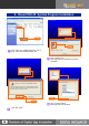
CD File Contents ( only for RCOM PRO20 (USB) Model) 4 1 There is PC program user’s manual. 2 Click x 2 3 4 You can find it with double click. 5 CD Contents 1 5 There is a file for installing USB driver. This program is for installing Font on your PC program. Click x 2 It will be installing with double click.. Refer to the page 7 for how to install. 2 Click Select XP folder. Refer to the user’s manual Page 4 for how to install.
2. Driver Installing (Automatic) Use manual driver installation when it cannot process automatic driver installation. USB Driver Installment file 1 Select “Auto_Setup(USB Drive)” file above window explorer. 4 Connect the incubator with computer USB port. The computer will recognize the incubator after a while. CAUTION Click 2 Click “Auto_Setup(USB Drive) file. 3 If the message above shows, it means installment is completed.
2. Driver Installing (Manual) Click 1 1 Connect the computer port and the incubator port. (Be sure to the power code is connected with incubator.) Click CAUTION 2 3 You would better to specify one USB port for use. Do not change USB port position. 1 After a few seconds, the message will appear as above. Then, check on “Install From a list or specific Location [Advanced]”. 2 Click “NEXT”. Click 2 1 Click 2 If you connect USB, “Found New Hardware” message will appear as above.
Be sure to select proper folder to user’s operation system. 1 Click 5 Click 2 7 Driver Installing will be executed. Select Driver CD or downloaded folder. 1 Select proper folder to your computer’s operating system from the Driver folder. EX) Windows XP – XP Folder Windows 98 – Win98_Me 2 Click “OK” button. Click Click 8 It will complete the primary Driver installing. 9 Soon, “Found New Hardware” message will appear again. 1 Click 6 2 After Driver folder selected, press “Next” button.
Click 1 Click 2 After a few seconds, the message will appear as above, again. 1 Check “Install From a list or specific Location [Advanced]” and then, click “Next”. 10 12 Driver installing will be executed. 2 Click “Next” button. Click 1 Click 13 Click 2 11 1 Confirm that “Include this location in the search” is marked. 2 Click “Next” button.
3. Rcom PRO20 Font Installation Click 1 Double click “Fonts exe file” on the given CD, or Downloaded file. It will execute and indicate as below. 4 Click 2 Click Here, click “Install” button. 5 Click 3 Program installation progress bar will be working, and 100% completed mark will show up, soon. . And, click “Next” button. Installation completed message will show up. Then, press “OK” button. All font installation completed.
4. Rcom PRO 20 System Program Installation Click Click 1 Click “Setup exe” installing file on the path of given CD or downloaded installing file. 3 Click computer icon. Next stage will be progressed for program Installation. Click Click 4 2 9 Click “OK” button. Click “Continue” button. Next stage will be progressed.
5 Program installation will be progressed and bar will be indicated. Confim Click 6 Program installation completed message will show up. Press “Confirm” button. CAUTION Be sure to reboot the computer after you complete program installation. CAUTION If the program does not executed well even if you reboot the computer, try to reboot the computer one more time.
5. Communication Linkage between Incubator and Computer 1 Connect the computer and USB cable on the state of power cable connecting. CAUTION Be sure to connect USB and incubator before starting program operation. 3 CAUTION When you execute the program first, Com1~10 will be indicated on condition window for seeking incubation connecting. If black display gives the figure of Temp. and humidity about 10~20sec.
Click 3 확인 2 Click 1 5 If the computer didn’t connect with incubator automatically, you need to connect manually. For manual connection, input password at the top. Password is made of compounding of the date and minute. Refer to the example below, and input password. Then, logo setup window will be unlocked, and you can manually set up. Click 6 1 For connecting communication manually, press Com1~ Com 10 button in order at 5sec. intervals. ) icon 2 On the communication linkage, ( will appear.
6. How to Incubate Easily with PC Click 2 Project Data Input 1 Click 1 1 3 1 For input new project, click “New” button. 2 Input the project data. Click 1 After setting completing, press “SAVE” button. 2 All preparing completed for starting incubation. Press “Start” button. Select 4 2 If the incubation is started, “Start” button will be disabled. And the Signal Bar, located at the top of “Status” blinks with red and blue color and progresses incubation.
7. Explanation of Each Part 1 Fundamental Terms of each part On the Main Screen 2 1 3 4 6 7 5 8 9 1 RCOM Logo Button : Basic conditions setting and testing. (Refer to the page 17.) 2 3 Status : Real-time display of incubator Temp. humidity, egg-turning intervals & angle, D-Day, and others conditions. Setting : Selecting the species of birds, Temp. mode (Standard mode or Special mode), Egg size, Working Mode (Automatic, Manual, or PC connecting). You also can setup temp.
2 Main Screen Project Input and Egg Data Input 15 1 3 4 2 6 7 5 7 10 15 12 7 9 8 11 12 10 9 8 11 12 13 10 1 Output project name. 5, which is on right top, is project No. 2 Input bird name, species, acquired date, acquired farm, manager, and laid date. 3 Egg No. which you selected on 15 , on the incubator icon. 4 Input selected egg’s laid date, length, width, hatch day, mother bird, and remarks. 5 For checking hatching success or failure.
3 Setup Window and Button on Main Screen 7 8 9 10 11 12 14 1 5 4 1 Indication for Information inputted eggs. 2 After all setting is completed, press “Start” button to start incubation. 3 After hatching, press this button for Incubation Termination. 4 Selecting Database input window and Graph window. 3 6 16 17 13 15 2 11 Changing the Temp. setting value. Automatic working mode : 36.5℃ ~ 38.5℃ Manual, PC working mode : 20.0℃ ~ 42.0℃ 12 Changing the humidity setting value.
4 Name of each parts on the Graphic screen 1 Click 2 3 4 5 6 7 17 1 “Graph” button functions convert Graph screen and DB screen. If you click, it makes a graph of setting Temp. &humidity as above, and also makes a graph of real-time incubator Temp. &humidity at 10min. intervals. 2 Indicating temp. &humidity graph setting value. Indicating incubator real-time temperature & humidity at 10min. intervals. 3 Selected graph’s project No. and name. 4 Button for move and select project.
5 Part explanation of Egg-Turning Screen 3 Click 2 5 Click Click 1 4 1 “Egg Turn” performs “Graph” and “Egg Turn” alternatively by turns with pressing the button. 2 Press “Setting” button to revise setting.( This button performs “Setting” and “Confirm” alternatively by turns.) 3 Set the egg-turning angle by pressing setting bar up/down button. (If you check RND, egg-turning angle will be various every time. 4 Confirm the egg-turning angle with the naked eye.
6 Egg Weight Loss & Density Loss Graph 6 5 3 1 7 2 3 6 5 1 4 7 2 3 19 1 Indicating Project related Data. 2 “Total Loss Average” button indicates all egg’s average weight & density loss with graph. 3 “Select Egg Loss” button indicates selected egg’s weight& density loss. 4 Indicating selected egg or total egg’s weight &density loss with graph. 5 Setting for targeted weight & density loss value. (You can control the value with the right control bar button.
1 Function explanation of Logo window 1 2 3 4 5 11 6 7 12 8 9 10 1 Input the password for default value setting. (Refer to the page9 for how to set the password.) 2 This button automatically connect for communicating with incubator. If there is no sign on the screen, press this button. It connects by searching for connection port. 3 Manual connection is available when automatic connection is failed. Press at 5 sec. intervals one by one. After connecting, ”COM_OK” icon will show up.
8. Start Incubation 1 Preparing for incubation start Confirm 1 4 3 2 1 modify Input Click 2 At first, confirm the incubator is connected with your computer normally. ( Computer icon on the screen means successfully connected.) (If the incubator is not successfully connected with the computer, you can not start incubation.) Press “New” button. 3 Input incubation related data, such as project name, bird name, and species, etc.
2 Incubation conditions set up on setting part 1 Select Click Click 7 2 Adjustment 3 Click 6 4 5 1 Select the species of birds. If you select the species of birds, the bird’s incubation data which is inputted on “Logo” part will be set as setting value. (Temp. humidity, egg-turning angle& interval will be set automatically.) 2 Even if the setting value set up automatically, you can modify each setting value.
9. Special Mode Setting of Temperature and Humidity 2 4 Click 8 Click 1 9 Click 3 10 6 7 5 1 If you click “Graph/DB” button, Graph screen will show up. 2 When you press “Setting” button, the button name will be changed by “PC-Confirm”, and blue bar will be indicated for setting. 3 Click Point for controlling temp. &humidity on the date what you want to control. If you move your mouse up or down, graph will go with the mouse. Click the Point one more on the position where you want to set.
2 Graph Temp. & Humidity Setting Value Change on Special Mode 6 3 2 4 5 Click 1 Click 1 Click 1 Click temp. or humidity Point which you want to modify, and move up or down. Then, graph will move together. Now, click your mouse one more time on the modifying position. Temp.& humidity will be set on that position. 2 For modifying temperature or humidity graph value, click Point and move it. Then, it indicates current temp.& humidity change value.
10. Real-time Temperature & Humidity Indication 1 Real-time Graph screen - Name explanation 4 1 2 3 1 5 1 It indicates real-time temperature and humidity change value with graph. As temp. or humidity setting graph indicates real-time value, you can check exact declination with the graph. 2 It indicates temp. humidity, and egg turning setting value & change value with graph. 3 It indicates daily temp.& humidity setting value and real-time change value for 24hours per an hour for selected egg.
11. Setting Change under Incubation 3 4 Click 1 Click 2 Click 1 Press “Setting” button on “PC-Confirm” (This button converts “Confirm” into ”Setting” ) 2 Click the temp.& humidity graph’s Point which you want to modify and move up or down. If you click one more time, temp. & humidity will be set on that position. 3 You can reset the species of birds, Temp. mode, temperature, humidity, incubation period, egg-turning angle & interval. ( You cannot modify egg size or working mode under incubation.
12. Egg Data Management 1 Input Egg Data 2 Click 3 Click Input 1 4 Click 5 27 1 Press “Add” button for adding egg data. 2 Select the egg which you will input data. Select the egg on incubator picture as above with your mouse. When you select, the egg number will be indicated on “Egg No.” in “Egg Info.” Box. 3 Input egg related basic data. Measure egg length and width with measuring instrument like vernier calipers. Input mother bird’s name, species, and remark.
2 Egg Selecting or Moving 1 2 6 3 4 5 1 If you select an egg for data input, move your mouse on the egg in the left incubator picture as above. Then, the mouse pointer will change like an arrow, and selecting is available. If you select an egg, it changes to yellow color. 2 If you move mouse pointer on an egg, it indicates its egg No. 3 Move to the first or last egg data. If there are subordinate data (daily egg weight data), it is connected and move together.
13. Egg weight & Density Loss Techniques 1 Weight Data Input 2 Input 1 Click 3 Click 2 15 9 17 19 2006-06-04 43.7 2006-06-05 43.2 1 Press before input selected weight data. 2 Input selected egg’s daily weight data. Input weight measurement date and figure to one decimal places. Saving data. 3 2006-06-09 41.5 12 6 4 2006-06-06 42.7 2006-06-07 42.3 2006-06-08 41.9 2006-06-10 41.1 2 2006-06-25 34.
2 Weight Loss Technique – Name explanation 9 5 10 4 6 7 8 11 12 3 1 2 13 1 Indicating basic data about selected project. 2 All egg’s average weight loss graph in the project. 3 Selected egg’s weight loss graph in the same project. 4 Initial weigh value. 5 Targeted weight loss value. 6 Weight loss setting graph. You can change the targeted value by using setting bar. 7 Indicating weight loss with graph. 8 You can change the targeted value by setting bar.
3 Density Loss Technique- Name explanation 9 5 10 4 6 7 8 11 12 3 1 31 13 1 Indicating basic data about selected project. 2 All egg’s average density loss graph in the project. 3 Selected egg’s density loss graph in the same project. 4 Initial density value. 5 Targeted density loss value. 6 Density loss setting graph. You can change the targeted value by using setting bar. 7 Indicating density loss with graph. 8 You can change the targeted density loss value by setting bar.
14. Terminating Incubation 2 3 1 Click 4 1 This button is for terminating incubation. After incubation termination, all incubation data such as real-time value, temperature, humidity, and setting graph etc. will remain as DB. You can use this same conditions later when you want to incubate. 2 After incubation termination, blue Signal bar will be changed to red signal bar and do not flash anymore. 3 Project name will disappear from “Status” of incubator.
15. Upgrading Firmware 4 1 Press “MENU” button without power connecting. Connect the USB port. When you upgrade firmware, connect USB port Between 1 and 4. (Generally, 1~4 are at the back side of PC, and USB port No. will change according to the position.) CAUTION Be sure to install USB driver before upgrading firmware. CAUTION 2 If you operate the computer with firmware upgrade, it doesn’t work. Before upgrading, screen saver has to stop working.
Click RCOM Manager File 6 Select “RCOM_Manager” file above Window explorer. 10 Select Firmware file and click “Update(U)” button. 11 Wait a while during updating is on process. New version Incubator (about 9min. is needed) Old version Incubator (about 19min. is needed) Click 7 Double-click “RCOM_Manager” file. Click 8 The file as above will show. Click “File”. (Be sure to check the incubator is connected with PC through USB cable.) 12 The message shows, it means update is normally completed.
12. Troubleshooting 16. Alarms 1 2 Incubator View Window is opened. Be sure to cover the window. Short of water. Please add water. 4 Some error occurred in air circulation fan. Please contact to service center. Some error occurred in temperature sensor. Please contract to service center. 5 2 1 3 1. You started incubation not from the PC but from the incubator. In this case, the data can be different from the incubator. 2.
17. Troubleshooting Circumstance Solutions 1 Incubator doesn’t operate normally on the program. Take off incubator power cord and cut power supply. Put the power cord again after 1~2min. 2 Incubation starting alarm sounds more than 2 times. It can be various from connecting conditions between incubator and PC. But if it repeats continue, try to the solution No.1 3 There is no D-Day display and Bird icon on LCD. You added new( non registered) species of birds on program logo window.