INSTALLATION INSTRUCTIONS • Level Rail • Stair Rail ICC-ES Evaluation Report No.
LEVEL RAIL RDI has obtained an ICC evaluation report on the 2006 International Building Code® and the 2006 International Residential Code®. For a full report, see ICC-ES Evaluation Report No. ESR-1849 at www.icc-es.org.
1. 2. 3. Prepare all posts and mounting surfaces before installation. Establish the level placement of the lower rail so that there is no more than a 4" space* from the bottom of the rail to the standing surface (Fig. 1). Place the Bottom Rail across the opening where it is to be installed (Fig. 3). Measure from the mounting surface to the first baluster hole on each end (Fig. 4), and adjust until these dimensions are equal.
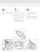
. 5. 6. Cut each end of the rail at the measurement determined in Step 3 (Fig. 7). Place a Bottom Mounting Bracket on each end of the Bottom Rail with the flat side facing the mounting surface (Fig. 8). Insert a baluster in each routed hole of the bottom rail (Fig. 11). Tip: If using a power saw, a carbide tip blade of at least 60 teeth is recommended. Place on the marks determined in Step 2. Pre-drill the holes (Fig.
7. 8. 9. If you did not cut the top rail in steps 3 and 4, do so now following the same procedure you used in steps 3 and 4 for the bottom rail. Place a T-shaped mounting bracket on each end of the top rail, with the flat side facing the mounting surface. Slide the bracket back past the first baluster hole (Fig. 12). Beginning at one end of the rail section, (Fig. 14) insert each baluster installed in Step 6 into the corresponding baluster hole in the top rail.
10. Check entire installation for accuracy before snapping Screw Head Covers (Fig. 17) into place. (Fig.
STAIR RAIL RDI has obtained an ICC evaluation report on the 2006 International Building Code® and the 2006 International Residential Code®. For a full report, see ICC-ES Evaluation Report No. ESR-1849 at www.icc-es.org.
1. 2. Prepare all posts and mounting surfaces before installation. Temporarily secure a plank on the noses of the stairs between the posts onto which you are installing the stair rail. (Fig. 1) The thickness of the plank will determine the space between the stairs and the bottom rail. Place the Bottom Rail, baluster holes facing up, on the plank with the sticker reading “this end at the top” at the top post (Fig. 2). Slide the rail up or down until the baluster hole spacing is even on each end (Fig. 3).
3. 4. 5. Align a Bottom Mounting Bracket with one end of the rail. Trace the rail end onto the bracket face, (Fig. 6) and adjust bracket up or down as needed to ensure a proper fit. Place the brackets from Step 3 on each end of the rail, flat side facing the mounting surface. Pre-drill the holes for the mounting brackets to avoid stripping the stainless steel screws and secure in place (Fig. 8, 9).
6. 7. 8. Leave the mounting brackets taped in place and cut the top rail to fit (Fig. 13). Pull the bracket back from each end approximately 1/4" from the end. Trace the retaining pin channel onto the rail sleeve, and mark 5/16" from the end of the rail (Fig. 14). Insert a Square Baluster in each rout of the bottom rail. Each kit contains 2 crimped balusters; space them evenly in each section.
9. 10. To allow for baluster expansion, raise the top rail approximately 1/8". Pre-drill the holes for the mounting brackets to avoid stripping the stainless steel screws, and secure in place (Fig. 17, 18). Check entire installation for accuracy before snapping Screw Head Covers (Fig. 19) into place. (Fig. 17) (Fig. 18) (Fig.
RAILING DYNAMICS, INC. FOR HOME, FOR LIFE™ 135 STEELMANVILLE ROAD EGG HARBOR TOWNSHIP, NJ 08234 TEL: (877) 420-7245 FAX: (866) 277-5160 E-MAIL: CS@RDIRAIL.COM URL: WWW.RDIRAIL.COM EMIOR/9.