TM TRANSFORM INSTALLATION INSTRUCTIONS • • • • Level Rail ......................................... 2 Level Angle ....................................... 8 Stair Rail .......................................... 9 Care & Maintenance, Finishing ......
Need a little help installing your railing? www.rdirail.com/support/installation-videos.html LEVEL RAIL Transform is designed to exceed the most stringent building codes. For most installations everything you need is in the box. When installing spans that are greater than 91" under certain International Building Code conditions, an additional stiffener* may be necessary. Please check Transform’s CCR report for the most up to date technical information and install accordingly.
LEVEL RAIL KITS 1. 2. 3. Prepare all posts and mounting surfaces before installation. If using a trim ring, be sure to install trim ring prior to fastening bottom beam. Establish the level placement of the lower rail so that there is no more than a 4" space from the bottom of the rail to the standing surface. Mark the post or mounting surface at this dimension to determine the bottom rail height (Fig. 1).
. 5. 6. Place the bottom rail (B) across the opening where the railing is to be installed (Fig. 3). Measure from the mounting surface to the first baluster hole on each end and adjust until these dimensions are equal. Trace the post edge onto the bottom rail (B) at each end (Fig. 4). Ensure all mounting surfaces are plumb. Transfer your measurements and baluster layout from the bottom rail (B) to the top beam (D) (Fig. 5) ensuring the baluster slots are aligned.
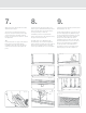
7. 8. 9. Align the bottom beam with the marks determined in Step 2. Cut the bottom rail support (K) to the bottom space determined in Step 2 and place it under the bottom beam at the center point (Fig. 11 and 12). Snap the bottom rail (B) over the bottom beam (D) (Fig. 14, 15). Secure the lower bracket & beam to the post using 6 mounting screws (G), 3 per bracket (Fig. 9). Begin with the bottom center screw as shown to avoid misalignment.
10. 11. 12. Place the top beam into position and align the top of the baluster plugs with the routed slots and snap into place (Fig. 19). For round balusters, ensure the baluster shoes (sold separately) are on both ends of the balusters to properly lock balusters in place in the rail section. Secure the upper bracket & beam to the post using 6 mounting screws (G), 3 per bracket (Fig. 19). Begin with the bottom center screw as shown to avoid misalignment.
13. 14. 15. If needed, an additional rail stiffener (N) can be purchased separately, and installed in place in top rail (A) as shown below. Snap the top rail (A) onto the top beam (D). Work from one end of the rail to the other until the full length of the top rail locks into place (Fig. 24). Using the painted screws (J) install two of the screws upward from underneath through the pre-drilled location. This will secure the bracket, beam, and top rail together (Fig. 25).
LEVEL ANGLE INSTALLATION Brackets are designed for use in level angle applications up to 45°. Note that the Presence and Aspire top rails will not fit on a 5" x 5" post if cut at 45°. Emerge top rail can be cut to 45° and mounted on a 5" x 5" post. 1. 2. 3. Secure brackets into beam using masking tape wrapped around bracket. Mark beam and bracket at desired level angle and cut. Install set screws to wider side of bracket only, as shown in Figure 3, to secure bracket to beam.
Need a little help installing your railing? www.rdirail.com/support/installation-videos.html STAIR RAIL Transform is designed to exceed the most stringent building codes. For most situations everything you need is in the box. When installing spans that are greater than 91" under certain International Building Code conditions, an additional stiffener may be necessary, please check Transform’s CCR report for the most up to date technical information and install accordingly.
STAIR KITS 1. 2. 3. Prepare all posts and mounting surfaces before installation. If using a trim ring, be sure to install trim ring prior to fastening bottom rail. Temporarily secure a plank on the nose of the stairs along side of the posts onto which you are installing the stair rail (Fig. 1). The thickness of the plank will determine the space between the stairs and the bottom rail (Fig. 2). Center the bottom beam (C) on plank between posts with the flat surface of the bottom beam facing down.
4. 5. 6. Wrap enough masking tape around the bracket (Fig. 4) to make it slide snugly into the end of the beam. Slide the bracket into the end of the bottom beam. Align brackets with angle marked on beam (Fig. 5) so that when the cut is made, the entire face of the bracket is cut but as little material is removed as possible. With brackets secured into bottom beam, cut through the beam and bracket together on the marked line (Fig. 6) to establish your installation angle.
7. 8. 9. Place the bottom rail support (M) on the nose of the tread that is nearest to the center of the stair rail section. Trace the bottom of the beam onto the support and cut the support to match the angle. Place the cut support in position under the center of the bottom beam. NOTE: In 6' stair kits and stair baluster packs, balusters come pre-cut at an angle of 32°. If stairs are at a different angle, cut balusters at required angle.
10. 11. 12. Now, adjust top beam until the balusters are plumb (Fig. 19). Mark both ends of the top beam (D) on the inside face of the post where it will be mounted (Fig. 20). Now remove the top beam. Wrap enough masking tape around the brackets to make them slide snugly into the ends of the beam. Slide the brackets into the ends of the top beam. Align brackets with angle marked on beam (Fig.
13. 14. 15. Set the top beam (D) in place by inserting the first baluster plug (at the bottom post) in the corresponding baluster, setting it in place, and working towards the top (Fig. 25). Pre-drill downward using a 1/8" drill bit. Be sure to drill through the beam and bracket (Fig. 27). Snap the top rail (A) onto the top beam (D) by applying downward pressure. Work from the bottom of the stair to the top end of the rail until the full length of the cover locks into place (Fig. 29 & Fig. 30).
16. Using the painted screws (J) install two of the screws upward from underneath each end through the pre-drilled location. This will secure the bracket, beam, and top rail together (Fig. 31). Care & Maintenance: Acrylic capstock resins have good resistance to a variety of common cleaners and application environments. It is recommended that you test any cleaner in an inconspicuous area prior to cleaning Transform railing systems.
Need a little help installing your railing? www.rdirail.com/support/installation-videos.html RAILING DYNAMICS, INC. FOR HOME, FOR LIFE® 135 STEELMANVILLE ROAD EGG HARBOR TOWNSHIP, NJ 08234 TEL: (877) 420-7245 FAX: (866) 277-5160 E-MAIL: CS@RDIRAIL.COM URL: WWW.RDIRAIL.COM TM 34106947 / 12.