EC6000i®, EC7000i®, and EC7500i® Series Installation Guide
This manual, the EC6000i , EC7000i, and EC7500i Series Installation Guide, is intended for all units belonging to the EC6000i, EC7000i, and EC7500i family of products. EC6000i, EC7000i, EC7500i, ITMS, RDM, and the RDM logo are all registered trademarks of RDM Corporation. All other brand names and trademarks appearing in this guide are the property of their respective holders. Copyright© RDM Corporation, 2012 All rights reserved.
Contents Compliance Statements .................................................................. 2 Introduction ..................................................................................... 4 Requirements .................................................................................. 5 Setting Up the EC6000i, EC7000i, or EC7500i ............................... 6 Operating the Scanner ..................................................................
Compliance Statements FCC Compliance Statement NOTE for EC6000i , EC7000i, and EC7500i Series Scanners: This equipment has been tested and found to comply with the limits for a Class A digital device, pursuant to part 15 of the FCC Rules. These limits are designed to provide reasonable protection against harmful interference when the equipment is operated in a commercial environment.
The telephone company may make changes in its facilities, equipment, operations or procedures that could affect the operation of this equipment. If this happens the telephone company will provide advanced notice in order for you to make necessary modification to maintain uninterrupted service. Connection to party line service is subject to state tariffs. Contact the state public utility commission, public service commission or corporation commission for information.
Introduction The EC6000i®, the EC7000i®, and the EC7500i® Series Scanners are cost effective, feature rich, imaging solutions. Using RDM’s industry leading progressive MICR method and imaging technology, the EC6000i, the EC7000i, and the EC7500i Series Scanners are ideal for Check Electronification, Check Cashing, and Walk-in Bill Payment applications.
Requirements • • The EC6000i, the EC7000i, and the EC7500i units are for indoor use only. Keep the EC6000i, the EC7000i, and the EC7500i dry; avoid areas of high humidity. Do not remove any cabinetry other than the areas specified in this guide. Removing cabinetry other than the areas specified in this guide will void the warranty. Recommendations • • • This unit may be installed and programmed by a distributor (reseller) other than the original manufacturer.
Setting Up the EC6000i, EC7000i, or EC7500i To set up the EC6000i, the EC7000i, and the EC7500i, follow steps A – H. A. Choose a Location Locate your scanner in a place that: • has a flat surface, such as a countertop or table • is convenient for the scanner operator • offers adequate ventilation and protection from elements such as heat, dust, oil, or moisture • is close to a telephone line or network connection (depending on your unit) and power connections. B. Unpack the Shipping Box 1. 2. 3.
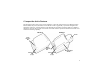
C. Inspect the Unit’s Features The illustrations below show a basic scanner (Model A), and an EC7500i scanner with a Magnetic Stripe Reader (MSR) and printer (Model B). Scanner Model A will be graphically represented throughout this manual for consistency. All other features of the EC6000i, the EC7000i, and the EC7500i are available as standard or optional. All EC7500i series models are franker-enabled. Specific EC6000i and EC7000i series models have franking capability.
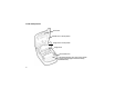
Inside Components Cover Latch Outside Cover in raised position Image Frame in raised position Image Sensor Document Sensors Document Feed Plate comes out to reveal optional Franking Acknowledgement Printer Assembly (EC6000i shown) 8
Connection Ports RDM’s EC6000i, the EC7000i, and EC7500i can be installed in different configurations. These configurations are set and programmed by the distributor (reseller) to suit your unique needs. Follow instructions provided by your distributor (reseller). EC6000i and EC7000i have the following ports: EC6000i and EC7000i Connectors Power: USB: AUX: COM: TEL: Red. Connect the power adaptor to this port. Orange. Use this port to connect to a PC. Yellow.
D. Insert the Franking Acknowledgement Printer Cartridge (Optional) The Franking Acknowledgement Printer Cartridge is an optional ink stamp, that marks the front of each check with a “Electronically Presented” message, or a message that you create. If you have purchased this option, follow these directions to insert the printer cartridge into the unit. I. Access the Printer Assembly 1. 2. 3. 10 Press the latch and lift the cover to access the imaging frame.
II. Insert the Franking Acknowledgement Printer Cartridge into the Printer Assembly 1. 2. 3. 4. 5. Insert the Franking Acknowledgment Printer Cartridge straight into the printer assembly. Apply pressure to the widest part of the flat top until the cartridge clicks into place. Replace the document feed plate by pressing down firmly until it clicks into place. Close the imaging frame. Close the outside cover. CAUTION: • Avoid contact with the main drive roller to prevent ink transfer to documents.
E. Connect to a Telephone Line (EC6014 and EC7014) FOR TEL: If you have purchased the EC6000i or the EC7000i with the optional modem, follow these directions to connect the telephone line. 1. Insert the end of the telephone line into the TEL port on the back of the scanner. 2. Insert the other end of the telephone line into a telephone jack in the wall. CAUTION: Plug the telephone line into an “outside line” analog phone jack only; the modem will not work if it is plugged into a PBX digital line.
F. Connect the Power Cord 1. 2. 3. 4. Insert the round end of the power cord into the power port on the back of the scanner. Align the flat side of the power connector facing up. Plug the metal-pronged end of the power cord into an electrical power outlet. When you connect to power, the LED lights up. Your unit is now powered on. CAUTION: Disconnecting the power source while the terminal is processing a transaction may cause data files stored in the unit’s memory to be lost.
G. Drivers The drivers for your scanner are installed when you install your PC application. If it is a Web-based application, ActiveX may be installed. There are many applications that support RDM EC Series Scanners; most are available from third-party vendors. If you are not sure where to acquire your PC application, check with the reseller from whom you purchased your scanner, your bank, or your service provider. H.
Operating the Scanner Preparing Checks To reduce the possibility of errors and damage to the unit, you should: • Remove all folds and creases in the check. • Remove any paper clips and staples from the check. Feeding Checks The scanner unit is ready to accept checks when the LED is green. Insert the check in the following way: • Flush to the right side of the scanner. • Information-side facing up. • MICR line to the inside right.
Status Signals for EC6000i and EC7000i The scanner comes equipped with the default light and sound signals described below. EC6000i/EC7000i Default Light Signals The unit’s status is shown through a single, multi-state LED (light-emitting diode), which is the light on the top, front, right-hand side of the unit. The table below describes typical status signals and their meanings.
EC6000i/EC7000i Default Sound Signals Several conditions are also signaled by a pattern of tones in addition to the LED display. Tone One short beep LED is flashing green Three short beeps LED is flashing red One long beep LED is flashing red Meaning The unit was successful in reading the MICR line. The unit was not successful in reading the MICR line. An error occurred during processing or storing of the captured image. A Typical Check Processing / LED Cycle for EC6000i/EC7000i 1. 2. 3.
Status Signals for EC7500i The scanner comes equipped with the default light and sound signals described below. Default Light Signals for EC7500i The unit’s status is shown through a single, multistate LED (light-emitting diode), which is the light on the top, front, right-hand side of the unit. The table below describes typical status signals and their meanings. This table applies to newer scanners. Older scanners cycle through the colors when they are powering up and waiting to connect and configure.
EC7500i Beeper Cues Single short beep - Indicates that a scanning exception or error has occurred. Check the scanning application display for instructions. A Typical Document Processing / LED Cycle for EC7500i 1. 2. 3. 4. The LED is Green (Solid): The unit is idle. The LED is Green (Flashing): The scanner is waiting for a document to be inserted for scanning. The LED is Green/Red (Flashing): The scanning operation is in progress. The LED is Green (Solid): The scanning operation is complete.
Maintaining the EC6000i, EC7000i, or EC7500i The EC6000i, EC7000i, or EC7500i performs best when all working surfaces are clean and free of foreign material. CAUTION: • Always disconnect the power to the scanner before cleaning it. Cleaning the Scanner • Solvents or harsh cleaners may damage or discolor the cabinetry. • • 20 To clean the outside cabinetry: Use a damp cloth and mild soap. To clean the inside of the unit: 1. Press the latch and lift the cover to access the imaging frame. 2.
Cleaning the Imager Occasionally, it may be necessary to clean the image sensors and remove dust or debris from the interior of the EC6000i, the EC7000i, or the EC7500i. To locate and access the document sensors: 1. Press the latch and lift the cover to access the imaging frame. 2. Lift imaging frame to access the document sensors. 3. Use a lens-cleaning tissue or a damp, lint-free cloth to remove any ink or dust from the document sensors or the main drive roller.
Troubleshooting In the course of everyday operations, you may encounter minor malfunctions in the EC6000i, the EC7000i, or the EC7500i unit. Before calling for service, review the troubleshooting steps below. Modem Does Not Function (EC6000i and EC7000i only) 1. 2. 3. Examine the telephone cord and all telephone connections to ensure that they are still connected properly.
Check Feeder Does Not Function Properly Ensure that you are inserting the check properly: flush to the right side of the EC6000i, the EC7000i, or the EC7500i, information-side facing up, with the MICR line to the inside right. If the problem persists, contact your distributor. Remove any debris by following the directions below: 1. Press the latch and lift the cover to access the imaging frame. 2. Lift the imaging frame to access Black Fingers Document the document feed plate. Sensors 3.
Card Transactions Do Not Function Properly Test the Card Swipe Mechanism 1. 2. 24 Ensure that you are swiping the card properly. The black magnetic stripe on the back of the card must face downward and to the left. Try using another card to ensure the first card was not defective.
Specifications EC6000i, EC7000i, EC7500i Specifications Unit Size Without MSR 8.6″ long x 6.1″ wide x 4.4″ high 21.9 cm long X 15.4 cm wide X 11.3 cm high With MSR 8.6″ long x 6.1″ wide x 5.3″ high 21.9 cm long x 15.4 cm wide x 13.5 cm high With Printer 11.8″ long x 6.1″ wide x 5.3″ high 30.1 cm long x 15.4 cm wide x 13.5 cm high Unit Weight EC6000i: 3.1 lbs. / 1.4 Kg EC7000i: 3.4 lbs. / 1.5 Kg EC7504i with printer: 6.0 lbs / 2.
Environmental Operating Temperature Operating Humidity Document Specifications Document Size and Weight 32 to 104 degrees F (0 to 40 degrees C). 10 to 85% relative humidity (non-condensing). Nominal: 2.16″ W x 4.4″ L (5.5 cm x 11.2 cm) Maximum: 4″ W x 9″ L (10.16 cm x 22.
(Optional) Modem Specifications Supports V.34bis, V.34 V.F.C, V.32bis, V.32, V.22bis, V.22A/B, V.23, V.21, Bell 212A and 103 Error Correction V.42 LAPM and MNP 2-4 Data Compression V.42bis and MNP 5 (Optional) Magnetic Stripe Reader (MSR) Specifications MSR Specifications 3 track, bi-directional Consumables Printer Roll Franking Acknowledgement Printer Cartridge Thermal, 2.
Warranty Information LIMITED WARRANTY: The RDM EC6000i units are warranted against defects in materials and workmanship under normal use and service for a period of one year after the date of receipt by you. The RDM EC7000i and EC7500i units are warranted against defects in materials and workmanship under normal use and service for a period of two years. This warranty is extended only to the original purchaser.
WARRANTY SPECIFICS: This warranty only covers failures due to defects in materials or workmanship, which occur during normal use.