Ready Access Portal Help Code No. LIT-12011342 Software Release 7.0 Issued December 5, 2014 Refer to the QuickLIT website for the most up-to-date version of this document. Ready Access Portal Help Introduction...................................................................................4 Concepts.....................................................................................................................................5 Ready Access Portal User Interface Overview...............................
Working in the Alerts Function Mode.............................................................................................23 Viewing Alerts.....................................................................................................................................23 Filtering Alerts.....................................................................................................................................23 Acknowledging Alerts...........................................................
HVAC Water Valves..........................................................................................................................277 Lighting..............................................................................................................................................291 Network.............................................................................................................................................297 Security.......................................................
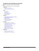
Ready Access Portal Help Introduction Welcome to the Release 7.0 Ready Access Portal Help. Click one of the following task section links to get started.
Tools: • Working in the Tools Function Mode Do you need general information on the Ready Access Portal user interface? Start at Ready Access Portal User Interface Overview. Are you looking for information on other actions not listed above? See Performing Other Actions. Curious about support for graphics? See Graphic View. Curious about support for Tailored Summaries? See Tailored Summary View. Having trouble? See Ready Access Portal Troubleshooting.
License Status Indicator The License Status indicator displays UNLICENSED if a piece of software on the Metasys® site is unlicensed. The unlicensed piece of software may be the Ready Access Portal itself or an Application and Data Server/Extended Application and Data Server (ADS/ADX) on the site. When the Ready Access Portal and all components of the Metasys site are licensed, the unlicensed message disappears. Dashboard Button Dashboard button (house): Opens the Dashboard or home view.
Note: Clicking the Back button does not log you out of the Ready Access Portal UI. See Logging Out. Name of Current User The name of the user currently logged on to the system appears on the Function bar just under the Logout button. Selection Area The Selection area contains the following: • • A drop-down list box that contains all user views present in the Site Director that have been assigned to you (currently logged on user).
Table 2: Workspace Title Bar Buttons 1 Description Button Set as Dashboard House and Arrow Sets the currently displayed view as the Dashboard. The Dashboard appears when you: • click the Dashboard button • log in to the system (the default view) For Metasys system Standard Access administrators, this button allows you set the Dashboard for yourself or other system users. This button does not appear for Tenant users.
For information on the system alert and status colors defined, refer to the Preferences section of the Metasys® SMP Help (LIT-1201793). Function Mode List The Dashboard displays a view from one of the function modes.
Timeout The Ready Access Portal UI supports the Never Terminate setting of a user profile in the Site Management Portal UI Security Administrator System. If a user is configured to never time out, and the user logs on to the Ready Access Portal UI, the user is never logged off due to inactivity. Note: The handheld Ready Access Portal UI does not support this functionality.
Consider the following behavior when you click the Set as Dashboard button: • The specific view in place when you click the Set as Dashboard button is the view that appears as the Dashboard. Example • • If a Device Summary view is visible when you click the Set as Dashboard button, the Device Summary is the view that appears as the Dashboard (as opposed to the Standard Summary view, which is the default view for the Summary function mode).
Alert Summary View Tasks The following task sections apply to the Alert Summary view: • Viewing Alerts • Filtering Alerts • Acknowledging Alerts • Discarding Alerts Alert Summary View Content The Workspace title bar displays the name of the Site Director as the context of the view. See Alert Summary View Content for details on the Alert Summary view.
The Summary function mode contains the following views: • Standard Summary view • Device Summary view • Tailored Summary view • Graphic view Standard Summary View The Standard Summary view contains information on objects directly inside the folder you select in the selection tree. If you click a link in the Value column and you have the appropriate privileges, you can change the value of the object.
Device Summary View Tasks The following task section applies to the Device Summary view: • Changing Item Values Device Summary View Content The Workspace title bar displays the name of the device you selected in the Standard Summary view as the context of the view. See Table 5 for details on the Device Summary view. Table 5: Device Summary View Content Column Details Icon Shows a picture corresponding to the type of item. The icons match icons used in the Site Management Portal UI.
• Changing Item Values • Adding a Temporary Override Graphic View Graphics appear in the user view tree as stand-alone items with a graphic symbol next to them ( for User Graphics Tool [UGT] graphics, and for Graphics Plus graphics) and in Tailored Summaries using the same symbols. See Tailored Summary View for details on Tailored Summaries in the Ready Access Portal UI. The Workspace title bar shows the word Graphics and then the name of the graphic, separated by a colon.
Table 6: Components of Display Control Tool Callout Name Description 1 Collapse Hides the Display Control tool. After you hide the tool, a faint arrow appears that allows you to restore the tool. 2 Fit to Window Zooms the graphic to fit in the frame. (center block) 3 Zoom Ball with Zoom Ring Allows you to zoom by moving the ball clockwise (zoom in) and counterclockwise (zoom out) along the zoom ring.
Schedule Summary View Tasks The following task sections apply to the Schedule Summary view: • Viewing Details for a Specific Schedule • Adding a Temporary Override Schedule Summary View Content The Workspace title bar displays the name of the folder you selected in the selection tree as the context of the view. See Table 7 for details on the Schedule Summary view. Table 7: Schedule Summary View Content Column Details Icon Shows a picture corresponding to a schedule.
Times in the Schedules function mode display in 24-hour time format. For example: • • • 00:00 is the start of the day 24:00 is the end of the day 12:00 is noon Note: See Ready Access Portal Troubleshooting if you would like to change the time format to 12-hour time. Note: For Release 6.0 or later, the display of Alerts, Schedules, and Trend Details includes the time zone. Today’s Schedule Tab The Today’s Schedule tab contains changes to the schedule for the current day, ending at 24:00.
Table 9: Temporary Overrides Tab Content Link/Column Description Daily End Shows the hour and minute of the day for the end of the override. This time is in terms of the days in the Starts On and Ends On fields. For the end of the day, select 24 for the Hour and 00 for the Minute. Value Lists the output value of the schedule during the override. Delete Temporary Override Allows you to delete the temporary override. Note: This column does not have a name.
Trend Summary View Tasks The following task section applies to the Trend Summary view: • Viewing Details on a Specific Trend Trend Summary View Content The Workspace title bar displays the name of the folder you select in the selection tree as the context of the view. See Table 11 for details on the Trend Summary view. Table 11: Trend Summary View Content Column Details Icon Shows a picture corresponding to the type of object that has a trended attribute.
Table 12: Trend Details View Content (Tabular Format) Column Details Time Displays the date and time that the trend collected the data sample. This column is sortable. Value Displays the data sample value. Tools Function Mode Tools Function Mode Overview The Tools function mode is accessible only by users with Metasys system Administrator access rights.
Dashboard: • Viewing Your Dashboard • Setting a View as Your Dashboard Alerts: • Viewing Alerts • Filtering Alerts • Acknowledging Alerts • Discarding Alerts Summary: • Viewing a Summary of Items in the System • Viewing Details for a Device • Viewing a Graphic • Changing Item Values Schedules: • Viewing a Summary of Schedules • Viewing Details for a Specific Schedule • Viewing Today’s Schedule • Viewing Temporary Overrides • Viewing Scheduled Items • Adding a Temporary Overrid
Viewing Your Dashboard To view your Dashboard, click the Dashboard button in the Function bar. Setting a View as Your Dashboard This task does not apply to Tenant users. A Metasys system Standard Access Administrator must set the Dashboard for a Tenant user. When a view is set as your Dashboard, the view appears as the default view when you log on and when you click the Dashboard function button (if present).
3. Click the check mark icon for that row ( ). 4. The view updates to remove the acknowledged alert. Discarding Alerts To discard alerts: 1. Click the Alerts function mode button in the Function bar. 2. Find the row for the alert you would like to discard. 3. Click the garbage can icon for that row ( ). 4. The view updates to remove the discarded alert.
1. In the Summary function mode, do one of the following: • In the Standard Summary view, click a link in the Value column; this allows you to change the value of the item you clicked. • In the Device Summary view, click a link in the Value column; this allows you to change the value of the item you clicked. • In the Tailored Summary view, click a link in a column; this allows you to change the value of the item you clicked.
Figure 3: Selecting a Trend to Add to the Trend Module If you want to open the Trend Module without adding or changing its content, click the Tools drop-down arrow on the Graphics+ Display Control tool (Figure 2) and select Trend. The Trend Module reappears in its last state and condition. For more details, see Trend Module Chart Functions and Trend Module Legend Functions. Trend Module Chart Functions See Figure 4 and Table 14 for explanations of the Trend Module chart components.
Figure 4: Graphics+ Trend Module - Chart Functions Table 14: Descriptions of Trend Module Chart Components Number Name Description 1 Plot Area Plots the trend data for all objects added to the Trend Module. 2 Box Zoom Zooms in for the area that is highlighted. To enable box zoom, place the cursor inside the plot area, hold down the mouse and drag left or right. A white shadow appears to outline the zoom area.
Table 14: Descriptions of Trend Module Chart Components Number Name Description 7 Right Y Axis (state data) Indicates the axis that is plotting the discrete states for objects currently displayed in the Trend Module. Metasys objects that are displayed on this axis typically consist of Boolean or multi-state values. 8 Right Pan Arrow Shifts the chart to display more recent trend data. 9 Newest Date/Time Displays date and time of the last value that appears on the chart.
Figure 5: Graphics+ Trend Module - Legend Functions Table 15: Descriptions of Trend Module Legend Components Number Name Description 1 Legend Splitter Bar Resizes the space taken by the legend. Move the splitter to the bottom or double-click the splitter bar to hide the legend and increase the size of the trend chart. 2 Legend Icons Display both the color and the y-axis that is used to display the trend data for the trended object in this row of the legend.
Table 15: Descriptions of Trend Module Legend Components Number Name Description 3 Show/Hide Trend Selects which objects currently appear in the chart. Click this box to hide and unhide trend data. 4 Object Name Displays the name for the trended Metasys object. When you click the object name (or its row), the corresponding line in the chart is highlighted. 5 Trend Name Displays the name of the trend that appears in the chart.
Figure 6: User Message: No Trend Data Available Trend Module Limitations The limitations of the Trend Module are as follows: • • • • • • A maximum of 500 data points can be displayed for a single trended object. No data older than 2 years can be displayed. The trend data originates from the device’s online buffer; samples stored in a historical database such as the JCIHistorianDB archive database are not included. You can open only one Trend Module per graphic.
Error Handling If an error occurs while stored trend samples are retrieved (for example, the bound trend object does not exist or its supervisory device is offline), the chart line for this trend series does not appear. The error message Could not retrieve trend information appears as a tooltip for the existing legend item. Closing the Trend Module You close the Trend Module by clicking the X in the upper-right corner of the Trend Module screen.
1. If you already have not done so, follow the steps in Viewing Details for a Specific Schedule to display the Schedule Details view. 2. Click the Temporary Overrides tab. Viewing Scheduled Items To view scheduled items: 1. If you already have not done so, follow the steps in Viewing Details for a Specific Schedule to display the Schedule Details view. 2. Click the Scheduled Items List tab. Adding a Temporary Override Note: You must have the appropriate privileges to add temporary overrides.
1. If you already have not done so, follow the steps in Viewing Details for a Specific Schedule to display the Schedule Details view. 2. Click the Temporary Overrides tab. 3. In the Delete Temporary Override column, click the garbage can icon ( ). A message appears stating that the temporary override is to be deleted permanently. 4. Click OK. The temporary override disappears and no longer affects the schedule.
Note: You can sort by a single column only. Note: If only the up arrow is white, the column is sorted in ascending order. If only the down arrow is white, the column is sorted in descending order. If neither arrow is white, the column is unsorted or restored to its default order. Paging through a View When scrolling does not display all items in a view, page links ( ) appear at the bottom. These links allow you to go to the previous/next page, first/last page, or a specific page of the view table.
Forced logouts happen in the following circumstances: • • • If a session times out, the user is logged off and returned to the logon screen. If the computer running the Ready Access Portal software restarts, users return to the login screen with their next click. After a Metasys system Administrator clicks the Start Update button, the Ready Access Portal logs the Metasys system Administrator out of the system immediately. All other users return to the logon screen with their next click.
Table 17: Ready Access Portal UI Troubleshooting Problem Solution You have problems accessing the Site Director and you see the following message: This problem occurs when the Site Director is offline or not communicating over the network. Cannot login: The Metasys site director device is To resolve this problem, the Metasys system Standard Access Administrator must make sure the Site Director is not available.
Table 17: Ready Access Portal UI Troubleshooting Problem Solution When you use Internet Explorer version 7 to display the Ready This message is a result of increased security in Internet Access Portal UI, a message appears in the Information bar warning Explorer version 7. you about active content. To resolve this problem: 1. Click the Information bar. 2. Select Allow Blocked Content.
Table 17: Ready Access Portal UI Troubleshooting Problem Solution You perform an action (click a link or button) and the login screen This behavior happens in the following circumstances: appears. • The Metasys system Administrator initiates an update. You make changes in the Site Director and update the Ready Access Portal UI, but the changes do not appear. • The computer running the Ready Access Portal software restarts. • The timeout period for the logged in user elapses.
Table 17: Ready Access Portal UI Troubleshooting Problem Solution You use the Back button to log in multiple users at the same time The Back button does not log a user off of the system. If you and devices on your Metasys network reset. use the Back button to log in multiple users at one time, Metasys system devices may exceed the number of supported simultaneous logged in users. If this occurs, the device may reset. Do not use the Back button to log in multiple users at one time.
Table 17: Ready Access Portal UI Troubleshooting Problem You would like to display the time in 12-hour format instead of 24-hour format. Solution To change the time display in the Ready Access Portal: 1. Open Notepad. 2. On the File menu, select Open. 3. Browse to C:\Program Files\Johnson Controls\Metasys RAP\release\web\web.config or C:\Program Files (x86)\Johnson Controls\Metasys RAP\release\web\web.config (Windows Server 2012 and Windows Server 2008 R2, 64-bit).
Graphics+ Runtime Help Reference The Graphics+ Runtime Help Reference describes the operational characteristics of Graphics+ elements as displayed in the Ready Access Portal user interface. This reference describes all of the elements found in Graphics+ objects created with the Graphic Generation Tool (GGT).
Note: You must have the Microsoft Silverlight 5.0 (or higher) plug-in to view Graphics+ objects created by the GGT. If you do not have the Silverlight 5.0 (or higher) plug-in installed, you are prompted to do so the first time you view a graphic. After you follow the prompt and install Silverlight 5.0 (or higher), log off the Metasys system, close your browser for the change to take effect, then log in to the Metasys system again.
The User Actions Panel lets you perform the following options for the bound Metasys item: • • • send a command navigate to its Focus window view its trend information If more than one trended attribute exists for the Metasys item, View Trend provides a drop-down list from which you can select the trended attribute (Figure 11). Figure 11: User Actions Panel with Multiple Trended Attributes On the Ready Access Portal, the types of objects you can navigate to and command are limited.
Library Elements • Basic Symbols • Electrical • Fire • Floor Plan • HVAC Air Coils • HVAC Air Sensors • HVAC Boilers • HVAC Chillers • HVAC Cooling Towers • HVAC Dampers • HVAC Ductwork • HVAC Fans • HVAC Heat Exchangers • HVAC Meters • HVAC Pipes • HVAC Water Pumps • HVAC Water Sensors • HVAC Water Valves • Lighting • Network • Security • Terminal Units Click a link in the following table for a description of the element.
Table 18: Library Elements Library Elements Barrier Barrier Alarm Basic Value Box Basic Fan Beam Detector Barrier Contact Battery Blind Flange Blind System Alarm Booster Pump Set Breaker Breaker Earth Leakage Building Button Card Reader Carrier® Chiller Check Valve Chiller Cleaver-Brooks® Boiler Combo Detector Computer Condensation Sensor Condenser Water Storage Connector (Small) Contactor Cooling Tower Day Sensor DC (Digital Controller) Deaerator Boiler Ready Access Portal Hel
Table 18: Library Elements Library Elements Differential Pressure Differential Pressure Sensor Differential Pressure Switch Diffuser - Round Diffuser - Square Disconnect Door Contact Down-Left Elbow Down-Right Elbow DT (Digital Terminal) Duct CO2 Duct Dew Point Duct Gas Draw Through Tower Duct Detector Duct Smoke Detector Duct Temperature and Humidity Duct Temperature Sensor DX DX Coil Electric Coil Electric Meter Elevator Alarm Emergency Call Disabled Toilet Emergency Light Fixture
Table 18: Library Elements Library Elements Filter Fin Tube Fire Damper Fire Detector Fire Panel Flag Alarm Indicator Flag Alarm Supply Floor Floor Group Flow Meter Flow Orifice Flow Paddle Wheel Flow Pressure Flow Switch (air) Flow Switch (water) Flow Switch (fire) Flow Ultrasonic Flow Venturi Fuse FX Gas Coil Gas Head Gas Meter Gas Panel General Alarm General Contact Generator Generator Fuel System Generic Boiler Generic Chiller Ready Access Portal Help: Graphic Enterprise Li
Table 18: Library Elements Library Elements Generic Sump Hand Valve, 2-Way Heat Cool Crossover Hand Valve, 3-Way Heat Detector Heat Exchanger Heating Manifold Heating-Cooling Coil Horizontal Opposed Damper Horizontal Parallel Damper Heat Meter Horizontal Level Switch Horizontal Pipe Horizontal Round Damper H-Stat Inline Command Box Humidity Sensor Image Integral Face and Bypass Coil Intruder Alarm Johnson Controls Logo Key Data Module IU Key Data Item Lamp Alarm Indicator Large Valve
Table 18: Library Elements Library Elements Light Switch Lighting Fixture Linear Gauge McQuay® Chiller MIG Manual Valve MIG (Old) Motion Sensor N2R N30 NAE/NIE - 55 series NCM Network Sensor Outside Air Temperature with Humidity Outside Air Temperature with Shield Overhead Door Contact Pegasys Controller NAE35/45/NCM45 NT Murray® Boiler Outside Air Temperature with Shield II Pipe Connector Pipe Heat Tape Plate Exchanger Pressure - Single Pressure Unit PRV Pull Station Pump Push
Table 18: Library Elements Library Elements Rain Gauge Sensor Rain Signal Remote Sump Tower Repair Switch Return Fan Roof Vent Down Roof Vent Up Rooftop Ice Storage Room CO2 Room Control Module (Multiple Rooms) Room Control Module Room Pressure Radiator Rectifier Semi-Circular Gauge RS9100 Thermostat Shell Exchanger Room Status Server Small Down-Left Elbow Small Blind Flange Small Horizontal Pipe Small Pipe Connector Small Up-Right Elbow Small Valve, 2-Way Electric Small Valve, 3-Way
Table 18: Library Elements Library Elements Small Vertical Pipe Smoke Detector Speaker Speaker with Strobe State Circle State Square Status Summary State Triangle Steam Humidifier Steam Meter Strobe Supply Fan Swipe Reader Switch Switch T4000 Thermostat Tamper Switch Tap TC (Terminal Controller) TC9100 Thermostat TE6700 Thermostat Temp Strap-on TEC Thermal Link Trane® Chiller Ready Access Portal Help: Graphic Enterprise Library Temperature Low Limit Sensor with Manual Reset TMZ The
Table 18: Library Elements Library Elements Ultrasonic Level Up-Right Elbow UNT Up-Left Elbow UPS UPS VAV - Single Duct UV Filter VAV - Dual Duct VAV Device Vertical Level Switch Vertical Motor Pump Vertical Opposed Damper Vertical Parallel Damper Vertical Pipe Vertical Pump Vertical/Horizontal Pump Vessel VMA1400 VMA1600 VND Wall Fan Water Coil Weather Station Weil-McClain® Boiler Ready Access Portal Help: Graphic Enterprise Library Water Meter Well Temperature 53
Table 18: Library Elements Library Elements Wind Direction Wind Gauge XT/XTM York® Chiller Ready Access Portal Help: Graphic Enterprise Library Window Contact 54
Basic Symbols This Library category includes the following elements: • Advanced Value Box • Basic Fan • Basic Value Box • Button • Image • Inline Command Box • Johnson Controls Logo • Key Data Module • Key Data Item • Linear Gauge • Semi-Circular Gauge • State Circle • State Square • State Triangle • Switch Ready Access Portal Help: Graphic Enterprise Library 55
Advanced Value Box This element represents an Advanced Value Box. It allows you to display information for one or two Metasys items (for example, zone temperature and zone temperature setpoint) and send commands to the items. Figure 12: Advanced Value Box - Single-Value Display Figure 13: Advanced Value Box - Two-Value Display The Advanced Value Box element has the following runtime characteristics: • • • • • • • It consists of one or two Inline Command Boxes.
Basic Fan This element represents a basic fan. The blades rotate when the fan is running and stop when the fan is off. Figure 14: Basic Fan The Basic Fan element has the following runtime characteristics: • • The color of the fan blades reflects the current value of the bound item (for example, stopped or running) as defined by the Fan Status section within Metasys system preferences. By default, green indicates a running fan and red a stopped fan.
Basic Value Box This element represents a Basic Value Box. Unlike other elements, it does not support commanding or navigating. Instead, it is used simply for the display of the current attribute value of a bound Metasys item, along with an optional indication of status. It functions as a simple, non-editable value box.
Button This element represents a Button. It allows you (with proper authorization) to navigate to a Metasys item, a URL, or an application. Figure 16: Button The Button element has the following runtime characteristics: • • • • • • • • • When the button is active, it brightens and changes to blue when you place your cursor over the button.
Image This element represents an Image. The Image element allows you to import an image and position it in the graphic. The image cannot exceed the allowed maximum size (1 MB), and only the following file types are supported within this element: Joint Photographic Experts Group (JPG or JPEG), Portable Network Graphics (PNG), Scalable Vector Graphics (SVG), and Compressed Scalable Vector Graphics (SVGZ).
Inline Command Box This element represents an Inline Command Box. It provides an interface that allows you to display the value of a Metasys item and send commands to that item. Figure 18: Inline Command Box The Inline Command Box element has the following runtime characteristics: • • • • • • • • It displays the current value of the bound item. It may display the status of the bound item. It may display the unit of measurement used for the bound attribute value.
Johnson Controls Logo This element represents the Johnson Controls® logo. Figure 19: Johnson Controls Logo The Johnson Controls Logo element has no runtime characteristics.
Key Data Item This element represents a Key Data Item. It provides a visual representation of bound data, and it consists of a label and an Inline Command Box. Figure 20: Key Data Item The Key Data Item element has the following runtime characteristics: • • • It displays a label on the left and an Inline Command Box on the right. For information about Inline Command Box functionality, see Inline Command Box. The location of the label is fixed to the left of the value box.
Key Data Module This element represents a Key Data Module. It provides a scrollable container for up to 50 key data items. Figure 21: Key Data Module The Key Data Module element has the following runtime characteristics: • • • • • It can be collapsed, expanded, or resized. It can be moved to another location on the graphic. It provides a vertical scroll bar (if needed) that allows you to view all listed items.
Linear Gauge This element represents a linear gauge in a vertical or horizontal orientation. It allows you to display information for a Metasys item (for example, zone temperature and zone temperature setpoint) within an analog bar and to send a command to the item. Depending on the orientation of the gauge, the minimum range is specified on the bottom or left and the maximum range is specified on the top or right. A value box appears at the bottom of the gauge.
Semi-Circular Gauge This element represents a semi-circular gauge in a horizontal orientation. It allows you to display information for a Metasys item (for example, zone temperature and zone temperature setpoint) within a semi-circular dial and to send a command to the item. The minimum range is specified on the left and the maximum range is specified on the right. A value box appears in the center of the gauge. The analog value needle is positioned according to the current value of the bound item.
State Circle This element represents a circle. The circle’s color indicates the current state of a Metasys item (for example, lights on or off and equipment running or stopped). Figure 24: State Circle The State Circle element has the following runtime characteristics: • • • • • Its color reflects the current value of the bound item (for example, State 1 or State 2) as defined by the circle’s State Color properties.
State Square This element represents a square. The square’s color indicates the current state of a Metasys item (for example, lights on or off or equipment running or stopped). Figure 25: State Square The State Square element has the following runtime characteristics: • • • • • Its color reflects the current value of the bound item (for example, State 1 or State 2) as defined by the square’s State Color properties.
State Triangle This element represents a triangle. The triangle’s color indicates the current state of a Metasys item (for example, lights on or off or equipment running or stopped). Figure 26: State Triangle The State Triangle element has the following runtime characteristics: • • • • • Its color reflects the current value of the bound item (for example, State 1 or State 2) as defined by the triangle’s State Color properties.
Switch This element represents a two- or three-position switch for conveying the current state of the bound Metasys item, and lets you send a command to the item. Figure 27: Switch The Switch element has the following runtime characteristics: • • • • • It displays the current value of the bound item by its switch position. It displays at the first switch position if the value is 0, displays at the second switch position if the value is 1, and displays at the third switch position if the value is 2.
Electrical This Library category includes the following elements: • Battery • Breaker • Breaker Earth Leakage • Connector (Small) • Contactor • Disconnect • Flag Alarm Indicator • Flag Alarm Supply • Fuse • Generator • Generator Fuel System • Lamp Alarm Indicator • Rectifier • Switch • Transformer • UPS Ready Access Portal Help: Graphic Enterprise Library 71
Battery This element represents a battery in an electrical drawing. Figure 28: Battery The Battery element has no Metasys bindings.
Breaker This element represents a circuit breaker in an electrical drawing. Figure 29: Breaker The Breaker element has the following runtime characteristics: • • • The background color of the element is set based on the status of the Status binding, along with the corresponding status color defined in Metasys system preferences for the Site. The foreground color of the element is always visible (for example, if the background color is black, then the foreground color of the element is white).
Breaker Earth Leakage This element represents an Earth Leakage Circuit Breaker (ELCB) in an electrical drawing. Figure 30: Breaker Earth Leakage The Breaker Earth Leakage element has no Metasys bindings. The Breaker Earth Leakage element has no runtime characteristics.
Connector (Small) This element represents cabling and the distribution of electricity. Figure 31: Connector (Small) The Connector (Small) element has no Metasys bindings. The Connector (Small) element has no runtime characteristics.
Contactor This element represents a single contact or single-pole switch for motor control. Figure 32: Contactor The Contactor element has the following runtime characteristics: • • • The background color of the element is set based on the status of the Status binding, along with the corresponding status color defined in Metasys system preferences for the Site.
Disconnect This element represents a disconnect switch. Figure 33: Disconnect The Disconnect element has the following runtime characteristics: • • • The background color of the element is set based on the status of the Status binding, along with the corresponding status color defined in Metasys system preferences for the Site. The foreground color of the element is always visible (for example, if the background color is black, then the foreground color of the element is white).
Flag Alarm Indicator This element represents a flag alarm indicator, which is used to indicate that there is a problem with a piece of equipment at a client site. Figure 34: Flag Alarm Indicator The Flag Alarm Indicator element has the following runtime characteristics: • When the value of the Status binding is: - Show - the flag alarm indicator appears. Hide - the flag alarm indicator does not appear.
Flag Alarm Supply This element represents a flag alarm supply, which is used to indicate that there is an issue with the electrical distribution at a client site. Figure 35: Flag Alarm Supply The Flag Alarm Supply element has the following runtime characteristics: • When the value of the Status binding is: - Show - the flag alarm supply appears. Hide - the flag alarm supply does not appear.
Fuse This element represents a fuse in an electrical drawing. Figure 36: Fuse The Fuse element has the following runtime characteristics: • • • The background color of the element is set based on the status of the Status binding, along with the corresponding status color defined in Metasys system preferences for the Site. The foreground color of the element is always visible (for example, if the background color is black, then the foreground color of the element is white).
Generator This element represents a generator in its three variations - electrical, diesel, or gas turbine. Figure 37: Generator - Electrical Figure 38: Generator - Diesel Figure 39: Generator - Gas Turbine The Generator element has the following runtime characteristics: • • • The background color of the circular portion of the element is static; it does not change to reflect the status of the bound item.
Generator Fuel System This element represents a generator fuel system. Figure 40: Generator Fuel System The Generator Fuel System element has the following runtime characteristics: • • When the element is bound to a Metasys item, the attached Advanced Value Boxes display all of their functionality. For information about Advanced Value Box functionality, see Advanced Value Box. When the value of the Status binding is: • - Off - the impellers do not spin. - On - the impellers spin.
Lamp Alarm Indicator This element represents a lamp alarm indicator, which is another method of indicating an alarm. Figure 41: Lamp Alarm Indicator The Lamp Alarm Indicator element has the following runtime characteristics: • When the value of the Status binding is: - Lit - the lamp alarm appears illuminated. Unlit - the lamp alarm appears dimmed.
Rectifier This element represents a rectifier in an electrical drawing. Figure 42: Rectifier The Rectifier element has no Metasys bindings. The Rectifier element has no runtime characteristics.
Switch This element represents a switch in an electrical drawing. Figure 43: Switch The Switch element has the following runtime characteristics: • • • The background color of the element is set based on the status of the Status binding, along with the corresponding status color defined in Metasys system preferences for the Site. The foreground color of the element is always visible (for example, if the background color is black, then the foreground color of the element is white).
Transformer This element represents a transformer in an electrical drawing. Figure 44: Transformer - Vertical Orientation Figure 45: Transformer - Horizontal Orientation The Transformer element has no Metasys bindings. The Transformer element has no runtime characteristics.
UPS This element represents an uninterruptible power supply (UPS). Figure 46: UPS The UPS element has no Metasys bindings. The UPS element has no runtime characteristics.
Fire This Library category includes the following elements: • Annunciator • Beam Detector • Combo Detector • Duct Detector • Fire Detector • Fire Panel • Flow Pressure • Flow Switch • General Alarm • General Contact • Heat Detector • Pull Station • Smoke Detector • Speaker • Speaker with Strobe • Strobe • Tamper Switch Ready Access Portal Help: Graphic Enterprise Library 88
Annunciator This element (depicted in its three available shapes) represents an annunciator. Figure 47: Annunciator The Annunciator element has the following runtime characteristics: • • • The background color of the element is set based on the status of the Value binding, along with the corresponding status color defined in Metasys system preferences for the Site.
Beam Detector This element (depicted in its three available shapes) represents a beam detector. Figure 48: Beam Detector The Beam Detector element has the following runtime characteristics: • • • The background color of the element is set based on the status of the Value binding, along with the corresponding status color defined in Metasys system preferences for the Site.
Combo Detector This element (depicted in its three available shapes) represents a combo detector, which detects both smoke and carbon monoxide (CO) gas in the air. Figure 49: Combo Detector The Combo Detector element has the following runtime characteristics: • • • The background color of the element is set based on the status of the Value binding, along with the corresponding status color defined in Metasys system preferences for the Site.
Duct Detector This element (depicted in its three available shapes) represents a duct detector, which detects smoke in an air duct system, thereby helping to prevent the spread of smoke and fire through the air duct system. Figure 50: Duct Detector The Duct Detector element has the following runtime characteristics: • • • The background color of the element is set based on the status of the Value binding, along with the corresponding status color defined in Metasys system preferences for the Site.
Fire Detector This element (depicted in its three available shapes) represents a fire detector, which detects fires and explosions. Figure 51: Fire Detector The Fire Detector element has the following runtime characteristics: • • • The background color of the element is set based on the status of the Value binding, along with the corresponding status color defined in Metasys system preferences for the Site.
Fire Panel This element (depicted in its three available shapes) represents a fire panel, which acts as the controlling component of a fire alarm system. Figure 52: Fire Panel The Fire Panel element has the following runtime characteristics: • • • The background color of the element is set based on the status of the Value binding, along with the corresponding status color defined in Metasys system preferences for the Site.
Flow Pressure This element (depicted in its three available shapes) represents a flow pressure device, which acts as the sensing element in a flow meter, or flow logger, to record the rate of fluid flow. Figure 53: Flow Pressure The Flow Pressure element has the following runtime characteristics: • • • The background color of the element is set based on the status of the Value binding, along with the corresponding status color defined in Metasys system preferences for the Site.
Flow Switch This element (depicted in its three available shapes) represents a flow switch, which monitors flow (for example, air, steam, or liquid) and sends a trip signal to another device, such as a pump or cooling circuit, to protect the device.
General Alarm This element (depicted in its three available shapes) represents a general alarm. Figure 55: General Alarm The General Alarm element has the following runtime characteristics: • • • The background color of the element is set based on the status of the Value binding, along with the corresponding status color defined in Metasys system preferences for the Site.
General Contact This element (depicted in its three available shapes) represents a general contact. Figure 56: General Contact The General Contact element has the following runtime characteristics: • • • The background color of the element is set based on the status of the Value binding, along with the corresponding status color defined in Metasys system preferences for the Site.
Heat Detector This element (depicted in its three available shapes) represents a heat detector, which responds to changes in ambient temperature by triggering an alarm signal. Figure 57: Heat Detector The Heat Detector element has the following runtime characteristics: • • • The background color of the element is set based on the status of the Value binding, along with the corresponding status color defined in Metasys system preferences for the Site.
Pull Station This element (depicted in its three available shapes) represents a pull station, which is a wall-mounted device that allows an alarm to be manually set off by anyone. Figure 58: Pull Station The Pull Station element has the following runtime characteristics: • • • The background color of the element is set based on the status of the Value binding, along with the corresponding status color defined in Metasys system preferences for the Site.
Smoke Detector This element (depicted in its three available shapes) represents a smoke detector, which detects smoke, typically as an indicator of fire. Figure 59: Smoke Detector The Smoke Detector element has the following runtime characteristics: • • • The background color of the element is set based on the status of the Value binding, along with the corresponding status color defined in Metasys system preferences for the Site.
Speaker This element (depicted in its three available shapes) represents a speaker, which broadcasts instructions during an emergency. Figure 60: Speaker The Speaker element has the following runtime characteristics: • • • The background color of the element is set based on the status of the Value binding, along with the corresponding status color defined in Metasys system preferences for the Site.
Speaker with Strobe This element (depicted in its three available shapes) represents a speaker with strobe, which broadcasts instructions and flashes during an emergency. Figure 61: Speaker with Strobe The Speaker with Strobe element has the following runtime characteristics: • • • The background color of the element is set based on the status of the Value binding, along with the corresponding status color defined in Metasys system preferences for the Site.
Strobe This element (depicted in its three available shapes) represents a strobe, which flashes during an emergency. Figure 62: Strobe The Strobe element has the following runtime characteristics: • • • The background color of the element is set based on the status of the Value binding, along with the corresponding status color defined in Metasys system preferences for the Site.
Tamper Switch This element (depicted in its three available shapes) represents a tamper switch, which mounts to AFD and LFD Series water flow devices to monitor removal of the cover. Figure 63: Tamper Switch The Tamper Switch element has the following runtime characteristics: • • • The background color of the element is set based on the status of the Value binding, along with the corresponding status color defined in Metasys system preferences for the Site.
Floor Plan This Library category includes the following elements: • Air Handler • Boiler • Building • Chiller • Cooling Tower • Diffuser - Round • Diffuser - Square • Fire Damper • Floor • Floor Group • Heat Exchanger • H-Stat • PRV • Pump • Room Control Module (Multiple Rooms) • Room Status • Status Summary • VAV - Dual Duct • VAV - Single Duct • Wall Fan Ready Access Portal Help: Graphic Enterprise Library 106
Air Handler This element represents an air handler, which conditions and circulates air as part of a HVAC system. This device is also known as an Air Handling Unit (AHU). Figure 64: Air Handler The Air Handler element has the following runtime characteristics: • • When the element is bound to a Metasys item, the attached Advanced Value Box displays all of its functionality. For information about Advanced Value Box functionality, see Advanced Value Box.
Boiler This element represents a boiler, which heats water for the purpose of providing heat to a facility. Figure 65: Boiler The Boiler element has the following runtime characteristics: • • When the element is bound to a Metasys item, the attached Advanced Value Box displays all of its functionality. For information about Advanced Value Box functionality, see Advanced Value Box. When the value of the Status binding is: - Off - the boiler’s flame is not visible.
Building This element represents a building within a site or campus. This element also provides an attached status summary to display summarized status data for the building. Figure 66: Building The Building element has the following runtime characteristics: • • • When the Item List is bound to one or more Metasys items, the attached Status Summary displays all of its functionality. For information about Status Summary functionality, see Status Summary.
Chiller This element represents a chiller, which removes heat from a liquid via a vapor-compression or absorption refrigeration cycle. Figure 67: Chiller The Chiller element has the following runtime characteristics: • • When the element is bound to a Metasys item, the attached Advanced Value Box displays all of its functionality. For information about Advanced Value Box functionality, see Advanced Value Box.
Cooling Tower This element represents a cooling tower, which removes heat from a building space by transferring process waste heat to the atmosphere. Figure 68: Cooling Tower The Cooling Tower element has the following runtime characteristics: • • When the element is bound to a Metasys item, the attached Advanced Value Boxes display all of their functionality. For information about Advanced Value Box functionality, see Advanced Value Box.
Diffuser - Round This element represents a round diffuser, which functions as part of a room air distribution subsystem. Figure 69: Diffuser - Round The Diffuser - Round element has no runtime characteristics.
Diffuser - Square This element represents a square diffuser, which functions as part of a room air distribution subsystem. Figure 70: Diffuser - Square The Diffuser - Square element has no runtime characteristics.
Fire Damper This element represents a fire damper, which closes during the threat of a fire and keeps burning debris from passing through it into another area of a building. It also limits the amount of fresh air that can feed an existing fire. Figure 71: Fire Damper The Fire Damper element has the following runtime characteristics: • • When the element is bound to a Metasys item, the attached Advanced Value Box displays all of its functionality.
Floor This element represents a floor. The element provides the user interface for displaying the background image, exterior walls, interior walls, and room statuses that make up a single floor (for information on how to customize a Floor element, refer to the Graphic Generation Tool Help [LIT-12011697]). This element also provides an attached status summary element to provide summarized status data for the floor.
Floor Group This element represents a floor group within a site or campus. This element also provides an attached status summary to display summarized status data for the group of floors. Figure 73: Floor Group The Floor Group element has the following runtime characteristics: • • • When the element is bound to a Metasys item, the attached Status Summary displays all of its functionality. For information about Status Summary functionality, see Status Summary.
Heat Exchanger This element represents a heat exchanger, which consists of multiple, thin, slightly separated plates that have large surface areas and fluid flow passages that are used for heat transfer. Figure 74: Heat Exchanger The Heat Exchanger element has the following runtime characteristics: • • When the element is bound to a Metasys item, the attached Advanced Value Box displays all of its functionality. For information about Advanced Value Box functionality, see Advanced Value Box.
H-Stat This element represents an h-stat device, which regulates the temperature of a system so that the system’s temperature is maintained near a desired setpoint temperature. Figure 75: H-Stat The H-Stat element has the following runtime characteristic: when the element is bound to a Metasys item, the attached Advanced Value Box displays all of its functionality. For information about Advanced Value Box functionality, see Advanced Value Box.
PRV This element represents a Pressure Reducing Valve (PRV), which reduces pressure in water supply mains. Figure 76: PRV The PRV element has no runtime characteristics.
Pump This element represents a water pump, which pumps large volumes of water to and from large pieces of equipment, such as chillers, boilers, heat exchangers, and cooling towers. Figure 77: Pump The Pump element has the following runtime characteristics: • • • When the element is bound to a Metasys item, the attached Advanced Value Boxes displays all of their functionality. For information about Advanced Value Box functionality, see Advanced Value Box.
Room Control Module (Multiple Rooms) This element displays general room information (such as zone temperature, alarm limits, and setpoints) for the currently selected Room Status element in the graphic. This Room Control Module is different from the Room Control Module in that its values dynamically update based on the selected room within a floor.
• - Alarm limits are unavailable. No Alarm information is configured. - Alarm limits are unavailable. Configured item could not be located. It displays a warning icon with a message if the Metasys item has misconfigured alarms or alarm limits. For example: Alarm extension is not configured correctly. The High Warning limit is greater than or equal to the High Alarm limit.
Room Status This element uses color to represent the current status of a zone/room of a floor plan governed by a sensor (for example, temperature, humidity, lighting).
Status Summary This element represents a status summary. The element provides the user interface for summarizing alarm, warning, and offline statuses for a list of Metasys item references. Figure 80: Status Summary Figure 81: Status Summary with Value Inaccessible Panel The Status Summary element has the following runtime characteristics: • • • • • The element counts and displays the number of items with an Alarm, Warning, or Offline status.
VAV - Dual Duct This element represents a variable air volume device with a dual-duct assembly. Figure 82: VAV - Dual Duct The VAV - Dual Duct element has no runtime characteristics.
VAV - Single Duct This element represents a variable air volume device with a single-duct assembly. Figure 83: VAV - Single Duct The VAV - Single Duct element has no runtime characteristics.
Wall Fan This element represents a simple wall fan. Figure 84: Wall Fan The Wall Fan element has the following runtime characteristics: • • When the element is bound to a Metasys item, the attached Advanced Value Box displays all of its functionality. For information about Advanced Value Box functionality, see Advanced Value Box. When the value of the Status binding is: - Off - the fan blades do not spin. On - the fan blades spin.
HVAC Air Coils This Library category includes the following elements: • DX Coil • Electric Coil • Gas Coil • Heating-Cooling Coil • Integral Face and Bypass Coil • Steam Humidifier • Water Coil Ready Access Portal Help: Graphic Enterprise Library 128
DX Coil This element represents a DX coil, which functions exclusively for cooling air. A DX coil contains up to eight stages. Each stage is a separate Metasys object. Figure 85: DX Coil The DX Coil element has the following runtime characteristics: For each of the eight DX stages, when the value of the Value binding is: • • Off - the cooling coil appears brown. On - the cooling coil appears blue.
Electric Coil This element represents an electric coil, which functions exclusively for heating air. An electric coil contains up to eight heating coils. Each heating coil is a separate Metasys object. Figure 86: Electric Coil The Electric Coil element has the following runtime characteristics: For each of the eight electric heating coils, when the value of the Value binding is: • • Off - the heating coil appears dark gray. On - the heating coil appears red/orange.
Gas Coil This element represents a gas coil, which functions exclusively for gas air. Figure 87: Gas Coil The Gas Coil has the following runtime characteristics: • Off - the heating coil appears dark gray. • On - the heating coil appears red/orange.
Heating-Cooling Coil This element represents a heating or cooling coil, which is used for heating or cooling air. Figure 88: Heating-Cooling Coil The Heating-Cooling Coil element has the following runtime characteristics: • • • When the element is bound to a Metasys item, the attached Advanced Value Boxes display all of their functionality. For information about Advanced Value Box functionality, see Advanced Value Box.
Integral Face and Bypass Coil This element represents an integral face and bypass coil, which alternates heating and bypass channels with face-and-bypass dampers before and after the coil. Figure 89: Integral Face and Bypass Coil The Integral Face and Bypass Coil element has the following runtime characteristics: • • When the element is bound to a Metasys item, the attached Advanced Value Boxes display all of their functionality.
Steam Humidifier This element represents a steam humidifier, which functions as part of a duct system by pumping steam into the air passing inside an air duct. Figure 90: Steam Humidifier The Steam Humidifier element has the following runtime characteristics: • • When the element is bound to a Metasys item, the attached Advanced Value Box displays all of its functionality. For information about Advanced Value Box functionality, see Advanced Value Box.
Water Coil This element represents a water coil, which is used for heating or cooling air. Figure 91: Water Coil The Water Coil element has the following runtime characteristics: • • • • When the element is bound to a Metasys item, the attached Advanced Value Box displays all of its functionality. For information about Advanced Value Box functionality, see Advanced Value Box. When the value of the Value binding within the Water Coil Primary binding group is: - Closed - none of the ten pipes is animated.
HVAC Air Sensors This Library category includes the following elements: • Air Velocity • Differential Pressure Sensor • Differential Pressure Switch • Duct CO2 • Duct Dew Point • Duct Gas • Duct Smoke Detector • Duct Temperature and Humidity • Duct Temperature Sensor • Flow Meter • Flow Switch • Humidity Sensor • Network Sensor • Outside Air Temperature with Humidity • Outside Air Temperature with Shield • Outside Air Temperature with Shield II • Rain Gauge Sensor • Rain S
Air Velocity This element represents an air velocity sensor, which measures the speed of the air inside an air duct. Figure 92: Air Velocity The Air Velocity element has the following runtime characteristic: when the element is bound to a Metasys item, the attached Advanced Value Box displays all of its functionality. For information about Advanced Value Box functionality, see Advanced Value Box.
Differential Pressure Sensor This element represents a differential pressure sensor, which measures air pressure at two locations and compares the two values. Figure 93: Differential Pressure Sensor The Differential Pressure Sensor element has the following runtime characteristic: when the element is bound to a Metasys item, the attached Advanced Value Box displays all of its functionality. For information about Advanced Value Box functionality, see Advanced Value Box.
Differential Pressure Switch This element represents a differential pressure switch, which measures the air pressure inside an air duct and compares it to the air pressure outside the air duct. Figure 94: Differential Pressure Switch The Differential Pressure Switch element has the following runtime characteristic: when the element is bound to a Metasys item, the attached Advanced Value Box displays all of its functionality. For information about Advanced Value Box functionality, see Advanced Value Box.
Duct CO2 This element represents a duct CO2 sensor, which monitors the level of carbon dioxide (CO2) in an air duct. Figure 95: Duct CO2 The Duct CO2 element has the following runtime characteristic: when the element is bound to a Metasys item, the attached Advanced Value Box displays all of its functionality. For information about Advanced Value Box functionality, see Advanced Value Box.
Duct Dew Point This element represents a duct dew point sensor, which measures the dew point inside an air duct. Figure 96: Duct Dew Point The Duct Dew Point element has the following runtime characteristic: when the element is bound to a Metasys item, the attached Advanced Value Box displays all of its functionality. For information about Advanced Value Box functionality, see Advanced Value Box.
Duct Gas This element represents a duct gas sensor, which measures the amount of gas, such as carbon monoxide, that is inside an air duct. Figure 97: Duct Gas The Duct Gas element has the following runtime characteristic: when the element is bound to a Metasys item, the attached Advanced Value Box displays all of its functionality. For information about Advanced Value Box functionality, see Advanced Value Box.
Duct Smoke Detector This element represents a duct smoke detector, which detects smoke inside an air duct. Figure 98: Duct Smoke Detector The Duct Smoke Detector element has the following runtime characteristic: when the element is bound to a Metasys item, the attached Advanced Value Box displays all of its functionality. For information about Advanced Value Box functionality, see Advanced Value Box.
Duct Temperature and Humidity This element represents a duct temperature and humidity sensor, which measures both the air temperature and humidity of the air passing through an air duct. Figure 99: Duct Temperature and Humidity The Duct Temperature and Humidity element has the following runtime characteristic: when the element is bound to a Metasys item, the attached Advanced Value Box displays all of its functionality. For information about Advanced Value Box functionality, see Advanced Value Box.
Duct Temperature Sensor This element (depicted in its two available configurations) represents a duct temperature sensor, which measures the air temperature inside an air duct. Figure 100: Duct Temperature Sensor - Averaging Figure 101: Duct Temperature Sensor - Bulb The Duct Temperature Sensor element has the following runtime characteristic: when the element is bound to a Metasys item, the attached Advanced Value Box displays all of its functionality.
Flow Meter This element represents a flow meter, which measures the speed of air flowing through a duct in a defined time segment. This meter is also known as an air consumption meter. Figure 102: Flow Meter The Flow Meter element has the following runtime characteristic: when the element is bound to a Metasys item, the attached Advanced Value Box displays all of its functionality. For information about Advanced Value Box functionality, see Advanced Value Box.
Flow Switch This element represents a flow switch, which measures the flow of air in a duct. Figure 103: Flow Switch The Flow Switch element has the following runtime characteristic: when the element is bound to a Metasys item, the attached Advanced Value Box displays all of its functionality. For information about Advanced Value Box functionality, see Advanced Value Box.
Humidity Sensor This element represents a humidity sensor, which monitors the humidity of air passing through an air duct. Figure 104: Humidity Sensor The Humidity Sensor element has the following runtime characteristic: when the element is bound to a Metasys item, the attached Advanced Value Box displays all of its functionality. For information about Advanced Value Box functionality, see Advanced Value Box.
Network Sensor This element represents a network sensor, which monitors the air temperature of a monitored space. Figure 105: Network Sensor The Network Sensor element has the following runtime characteristic: when the element is bound to a Metasys item, the attached Advanced Value Boxes display all of their functionality. For information about Advanced Value Box functionality, see Advanced Value Box.
Outside Air Temperature with Humidity This element represents an outside air temperature and humidity sensor, which measures both outside temperature (using a thermistor) and outside humidity (using a humidity transducer). Figure 106: Outside Air Temperature with Humidity The Outside Air Temperature with Humidity element has the following runtime characteristic: when the element is bound to a Metasys item, the attached Advanced Value Boxes display all of their functionality.
Outside Air Temperature with Shield This element represents an outside air temperature sensor with a shield, which measures outside temperature (using a thermistor). Figure 107: Outside Air Temperature with Shield The Outside Air Temperature with Shield element has the following runtime characteristic: when the element is bound to a Metasys item, the attached Advanced Value Box displays all of its functionality. For information about Advanced Value Box functionality, see Advanced Value Box.
Outside Air Temperature with Shield II This element represents an outside air temperature sensor with a shield, which measures outside temperature (using a thermistor). Figure 108: Outside Air Temperature with Shield II The Outside Air Temperature with Shield II element has the following runtime characteristic: when the element is bound to a Metasys item, the attached Advanced Value Box displays all of its functionality. For information about Advanced Value Box functionality, see Advanced Value Box.
Rain Gauge Sensor This element represents a rain gauge sensor, which measures the amount of rain that has fallen. Figure 109: Rain Gauge Sensor The Rain Gauge Sensor element has the following runtime characteristic: when the element is bound to a Metasys item, the attached Advanced Value Box displays all of its functionality. For information about Advanced Value Box functionality, see Advanced Value Box.
Rain Signal This element represents a rain signal device, which indicates whether or not it is raining. Figure 110: Rain Signal The Rain Signal element has the following runtime characteristic: when the element is bound to a Metasys item, the attached Advanced Value Box displays all of its functionality. For information about Advanced Value Box functionality, see Advanced Value Box.
Room CO2 This element represents a room CO2 sensor, which detects CO2 levels in an area. Figure 111: Room CO2 The Room CO2 element has the following runtime characteristic: when the element is bound to a Metasys item, the attached Advanced Value Box displays all of its functionality. For information about Advanced Value Box functionality, see Advanced Value Box.
Room Pressure This element represents a room pressure sensor, which provides monitoring and alarming for critical low differential pressure applications (for example, hospital patient isolation wards, pharmaceutical manufacturing, semiconductor fabrication, cleanrooms, and research laboratories). Figure 112: Room Pressure The Room Pressure element has the following runtime characteristic: when the element is bound to a Metasys item, the attached Advanced Value Box displays all of its functionality.
RS9100 Thermostat This element represents an RS9100 thermostat, which regulates the temperature of a room so that the room’s temperature is maintained near a desired setpoint temperature. Figure 113: RS9100 Thermostat The RS9100 Thermostat element has the following runtime characteristic: when the element is bound to a Metasys item, the attached Advanced Value Box displays all of its functionality. For information about Advanced Value Box functionality, see Advanced Value Box.
T4000 Thermostat This element represents a T4000 thermostat, which regulates the temperature of a room so that the room’s temperature is maintained near a desired setpoint temperature. Figure 114: T4000 Thermostat The T4000 Thermostat element has the following runtime characteristic: when the element is bound to a Metasys item, the attached Advanced Value Box displays all of its functionality. For information about Advanced Value Box functionality, see Advanced Value Box.
TC9100 Thermostat This element represents a TC9100 thermostat, which regulates the temperature of a room so that the room’s temperature is maintained near a desired setpoint temperature. Figure 115: TC9100 Thermostat The TC9100 Thermostat element has the following runtime characteristic: when the element is bound to a Metasys item, the attached Advanced Value Box displays all of its functionality. For information about Advanced Value Box functionality, see Advanced Value Box.
TE6700 Thermostat This element represents a TE6700 thermostat, which regulates the temperature of a room so that the room’s temperature is maintained near a desired setpoint temperature. Figure 116: TE6700 Thermostat The TE6700 Thermostat element has the following runtime characteristic: when the element is bound to a Metasys item, the attached Advanced Value Box displays all of its functionality. For information about Advanced Value Box functionality, see Advanced Value Box.
Temperature Low Limit Sensor with Manual Reset This element represents a temperature low limit sensor with manual reset, which acts as a switch for an air handler once the temperature gets too low. Figure 117: Temperature Low Limit Sensor with Manual Reset The Temperature Low Limit Sensor with Manual Reset element has the following runtime characteristic: when the element is bound to a Metasys item, the attached Advanced Value Box displays all of its functionality.
TMZ Thermostat This element represents a TMZ thermostat, which regulates the temperature of a room so that the room’s temperature is maintained near a desired setpoint temperature. Figure 118: TMZ Thermostat The TMZ Thermostat element has the following runtime characteristic: when the element is bound to a Metasys item, the attached Advanced Value Box displays all of its functionality. For information about Advanced Value Box functionality, see Advanced Value Box.
Weather Station This element represents a weather station, which consists of multiple air sensors in one assembly that measure various points of weather data, such as temperature, humidity, and wind speed. Figure 119: Weather Station The Weather Station element has the following runtime characteristics: • • When the element is bound to a Metasys item, the attached Advanced Value Boxes display all of their functionality. For information about Advanced Value Box functionality, see Advanced Value Box.
Wind Direction This element represents a wind direction sensor, which indicates the direction of the wind. Figure 120: Wind Direction The Wind Direction element has the following runtime characteristics: • • When the element is bound to a Metasys item, the attached Advanced Value Box displays all of its functionality. For information about Advanced Value Box functionality, see Advanced Value Box. When the value of the Value binding is: - North - the wind directional points north.
Wind Gauge This element represents a wind gauge, which measures wind speed. Figure 121: Wind Gauge The Wind Gauge element has the following runtime characteristics: • • When the element is bound to a Metasys item, the attached Advanced Value Box displays all of its functionality. For information about Advanced Value Box functionality, see Advanced Value Box. When the value of the Value binding is: - Off - the wind gauge does not spin. Low - the wind gauge spins slowly. High - the wind gauge spins fast.
HVAC Boilers This Library category includes the following elements: • Cleaver-Brooks® Boiler • Gas Head • Gas Panel • Generic Boiler • Heating Manifold • Murray® Boiler • Pressure Unit • Radiator • Thermal Link • Trane® Boiler • Weil-McClain® Boiler Equipment Notification Bindings for HVAC Boiler Elements The Equipment Notification panel displays at runtime when any of the bindings are triggered (for example, the value of the notification binding results in the animation being on).
Cleaver-Brooks® Boiler This element represents a Cleaver-Brooks boiler, which heats water for the purpose of providing heat. Figure 123: Cleaver-Brooks Boiler The Cleaver-Brooks Boiler element has the following runtime characteristics: • • When the element is bound to a Metasys item, the attached Advanced Value Box displays all of its functionality. For information about Advanced Value Box functionality, see Advanced Value Box.
Gas Head This element represents a gas head, which measures the quantity of gas used per unit time. Figure 124: Gas Head The Gas Head element has the following runtime characteristic: when the element is bound to a Metasys item, the attached Advanced Value Box displays all of its functionality. For information about Advanced Value Box functionality, see Advanced Value Box.
Gas Panel This element represents a gas panel, which separates supply gas into smaller lines and disperses it throughout a system. Figure 125: Gas Panel The Gas Panel element has the following runtime characteristic: when the element is bound to a Metasys item, the attached Advanced Value Box displays all of its functionality. For information about Advanced Value Box functionality, see Advanced Value Box.
Generic Boiler This element represents a generic boiler, which heats water for the purpose of providing heat. Figure 126: Generic Boiler The Generic Boiler element has the following runtime characteristics: • • When the element is bound to a Metasys item, the attached Advanced Value Box displays all of its functionality. For information about Advanced Value Box functionality, see Advanced Value Box. When the value of the Status binding is: • - Off - the boiler’s flame is not visible.
Heating Manifold This element represents a heating manifold, which uses supply water from a heat source, separates it into smaller lines, and disperses it throughout a radiant heat system. Figure 127: Heating Manifold The Heating Manifold element has no runtime characteristics.
Murray® Boiler This element represents a Murray boiler, which heats water for the purpose of providing heat. Figure 128: Murray Boiler The Murray Boiler element has the following runtime characteristics: • • When the element is bound to a Metasys item, the attached Advanced Value Box displays all of its functionality. For information about Advanced Value Box functionality, see Advanced Value Box. When the value of the Status binding is: • - Off - the boiler’s flame is not visible.
Pressure Unit This element represents a pressure unit, which measures the amount of pressure inside a gas pipe. Figure 129: Pressure Unit The Pressure Unit element has the following runtime characteristic: when the element is bound to a Metasys item, the attached Advanced Value Box displays all of its functionality. For information about Advanced Value Box functionality, see Advanced Value Box.
Radiator This element represents a radiator, which provides heat to a building by circulating hot water or steam generated in a central boiler. Figure 130: Radiator The Radiator element has the following runtime characteristic: when the element is bound to a Metasys item, the attached Advanced Value Box displays all of its functionality. For information about Advanced Value Box functionality, see Advanced Value Box.
Thermal Link This element represents a thermal link, which acts as a safety device in a boiler. If the boiler’s temperature is too high, the thermal link melts and breaks a circuit. Figure 131: Thermal Link The Thermal Link element has the following runtime characteristic: when the element is bound to a Metasys item, the attached Advanced Value Box displays all of its functionality. For information about Advanced Value Box functionality, see Advanced Value Box.
Trane® Boiler This element represents a Trane boiler, which heats water for the purpose of providing heat. Figure 132: Trane Boiler The Trane Boiler element has the following runtime characteristics: • • When the element is bound to a Metasys item, the attached Advanced Value Box displays all of its functionality. For information about Advanced Value Box functionality, see Advanced Value Box. When the value of the Status binding is: • - Off - the boiler’s flame is not visible.
Weil-McClain® Boiler This element represents a Weil-McClain boiler, which heats water for the purpose of providing heat. Figure 133: Weil-McClain Boiler The Weil-McClain Boiler element has the following runtime characteristics: • • When the element is bound to a Metasys item, the attached Advanced Value Box displays all of its functionality. For information about Advanced Value Box functionality, see Advanced Value Box.
HVAC Chillers This Library category includes the following elements: • Air-Cooled Chiller • Carrier® Chiller • Generic Chiller • McQuay® Chiller • Rooftop Ice Storage • Trane® Chiller • York® Chiller Equipment Notification Bindings for HVAC Chiller Elements The Equipment Notification panel displays at runtime when any of the bindings are triggered (for example, the value of the notification binding results in the animation being on).
Air-Cooled Chiller This element represents an air-cooled chiller, which removes heat from a liquid via a vapor-compression or absorption refrigeration cycle. Figure 135: Air-Cooled Chiller The Air-Cooled Chiller element has the following runtime characteristics: • • When the element is bound to a Metasys item, the attached Advanced Value Box displays all of its functionality. For information about Advanced Value Box functionality, see Advanced Value Box.
Carrier® Chiller This element represents a Carrier chiller, which removes heat from a liquid via a vapor-compression or absorption refrigeration cycle. Figure 136: Carrier Chiller The Carrier Chiller element has the following runtime characteristics: • • When the element is bound to a Metasys item, the attached Advanced Value Box displays all of its functionality. For information about Advanced Value Box functionality, see Advanced Value Box.
Generic Chiller This element represents a generic chiller, which removes heat from a liquid via a vapor-compression or absorption refrigeration cycle. Figure 137: Generic Chiller The Generic Chiller element has the following runtime characteristics: • • When the element is bound to a Metasys item, the attached Advanced Value Box displays all of its functionality. For information about Advanced Value Box functionality, see Advanced Value Box.
McQuay® Chiller This element represents a McQuay chiller, which removes heat from a liquid via a vapor-compression or absorption refrigeration cycle. Figure 138: McQuay Chiller The McQuay Chiller element has the following runtime characteristics: • • When the element is bound to a Metasys item, the attached Advanced Value Box displays all of its functionality. For information about Advanced Value Box functionality, see Advanced Value Box.
Rooftop Ice Storage This element represents a rooftop ice storage unit, which creates ice at night and stores it during the day. Figure 139: Rooftop Ice Storage The Rooftop Ice Storage element has the following runtime characteristics: • • When the element is bound to a Metasys item, the attached Advanced Value Boxes display all of their functionality. For information about Advanced Value Box functionality, see Advanced Value Box.
Trane® Chiller This element represents a Trane chiller, which removes heat from a liquid via a vapor-compression or absorption refrigeration cycle. Figure 140: Trane Chiller The Trane Chiller element has the following runtime characteristics: • • When the element is bound to a Metasys item, the attached Advanced Value Box displays all of its functionality. For information about Advanced Value Box functionality, see Advanced Value Box.
York® Chiller This element represents a York chiller, which removes heat from a liquid via a vapor-compression or absorption refrigeration cycle. Figure 141: York Chiller The York Chiller element has the following runtime characteristics: • • When the element is bound to a Metasys item, the attached Advanced Value Box displays all of its functionality. For information about Advanced Value Box functionality, see Advanced Value Box.
HVAC Cooling Towers This Library category includes the following elements: • Condenser Water Storage • Draw Through Tower • Generic Sump • Push Through Tower • Remote Sump Tower Equipment Notification Bindings for HVAC Cooling Towers Elements The Equipment Notification panel displays at runtime when any of the bindings are triggered (for example, the value of the notification binding results in the animation being on).
Condenser Water Storage This element represents a condenser water storage unit, which stores re-circulated water used in a chiller. Figure 143: Condenser Water Storage The Condenser Water Storage element has the following runtime characteristics: • • When the element is bound to a Metasys item, the attached Advanced Value Boxes display all of their functionality. For information about Advanced Value Box functionality, see Advanced Value Box.
Draw Through Tower This element represents a draw through tower, which acts as a heat removal device by transferring process waste heat to the atmosphere. Figure 144: Draw Through Tower The Draw Through Tower element has the following runtime characteristics: • • When the element is bound to a Metasys item, the attached Advanced Value Boxes display all of their functionality. For information about Advanced Value Box functionality, see Advanced Value Box.
Generic Sump This element represents a generic sump unit, which stores excess water from a cooling tower. Figure 145: Generic Sump The Generic Sump element has the following runtime characteristics: • • When the element is bound to a Metasys item, the attached Advanced Value Boxes display all of their functionality. For information about Advanced Value Box functionality, see Advanced Value Box.
Push Through Tower This element represents a push through tower, which acts as a heat removal device by transferring process waste heat to the atmosphere. Figure 146: Push Through Tower The Push Through Tower element has the following runtime characteristics: • • When the element is bound to a Metasys item, the attached Advanced Value Boxes display all of their functionality. For information about Advanced Value Box functionality, see Advanced Value Box.
Remote Sump Tower This element represents a remote sump tower, which consists of a cooling tower with a remote sump tank attached to it. The remote sump tank stores excess water for the cooling tower. Figure 147: Remote Sump Tower The Remote Sump Tower element has the following runtime characteristics: • • When the element is bound to a Metasys item, the attached Advanced Value Boxes display all of their functionality. For information about Advanced Value Box functionality, see Advanced Value Box.
HVAC Dampers This Library category includes the following elements: • Horizontal Opposed Damper • Horizontal Parallel Damper • Horizontal Round Damper • Vertical Opposed Damper • Vertical Parallel Damper Ready Access Portal Help: Graphic Enterprise Library 192
Horizontal Opposed Damper This element represents a horizontal opposed damper, which contains pairs of blades that open/close in opposite directions from each other. This damper regulates the flow of air inside a duct, chimney, VAV box, air handler, or other air handling equipment.
Horizontal Parallel Damper This element represents a horizontal parallel damper, which contains blades that open/close parallel to each other. This damper regulates the flow of air inside a duct, chimney, VAV box, air handler, or other air handling equipment. Figure 149: Horizontal Parallel Damper The Horizontal Parallel Damper element has the following runtime characteristics: • • When the element is bound to a Metasys item, the attached Advanced Value Box displays all of its functionality.
Horizontal Round Damper This element represents a horizontal round damper, which contains a single plate that pivots at its midpoint to either open or close. This damper regulates the flow of air inside a duct, chimney, VAV box, air handler, or other air handling equipment. Figure 150: Horizontal Round Damper The Horizontal Round Damper element has the following runtime characteristics: • • When the element is bound to a Metasys item, the attached Advanced Value Box displays all of its functionality.
Vertical Opposed Damper This element represents a vertical opposed damper, which contains pairs of blades that open/close in opposite directions from each other. This damper regulates the flow of air inside a duct, chimney, VAV box, air handler, or other air handling equipment. Figure 151: Vertical Opposed Damper The Vertical Opposed Damper element has the following runtime characteristics: • • When the element is bound to a Metasys item, the attached Advanced Value Box displays all of its functionality.
Vertical Parallel Damper This element represents a vertical parallel damper, which contains blades that open/close parallel to each other. This damper regulates the flow of air inside a duct, chimney, VAV box, air handler, or other air handling equipment. Figure 152: Vertical Parallel Damper The Vertical Parallel Damper element has the following runtime characteristics: • • When the element is bound to a Metasys item, the attached Advanced Value Box displays all of its functionality.
HVAC Ductwork This Library category includes the following elements: • Down Left • Down Right • Dual Path Left • Dual Path Right • Energy Recovery Wheel • Exhaust Down • Exhaust Up • Filter • Four Way Duct • Heat Cool Crossover • Horizontal Duct • Horizontal T Down • Horizontal T Up • Left Outlet • Right Outlet • Roof Vent Down • Roof Vent Up • Up Left • Up Right • UV Filter • Vertical Duct • Vertical T Left • Vertical T Right Ready Access Portal Help: Graphic E
Down Left This element represents a down left duct (an elbow duct with one end extending leftward and the other end extending downward), which functions as part of a duct system to deliver and remove air. Figure 153: Down Left The Down Left element has no runtime characteristics.
Down Right This element represents a down right duct (an elbow duct with one end extending rightward and the other end extending downward), which functions as part of a duct system to deliver and remove air. Figure 154: Down Right The Down Right element has no runtime characteristics.
Dual Path Left This element represents a dual path left duct (a horizontal duct with two ducts extending leftward and a single duct extending rightward), which functions as part of a duct system to deliver and remove air. Figure 155: Dual Path Left The Dual Path Left element has no runtime characteristics.
Dual Path Right This element represents a dual path right duct (a horizontal duct with two ducts extending rightward and a single duct extending leftward), which functions as part of a duct system to deliver and remove air. Figure 156: Dual Path Right The Dual Path Right element has no runtime characteristics.
Energy Recovery Wheel This element represents an energy recovery wheel, which uses the energy recovery process (exchanging the energy contained in normally exhausted building or space air) and treats the incoming outdoor ventilation air in residential and commercial HVAC systems. This device improves indoor air quality and reduces total HVAC equipment capacity.
Exhaust Down This element represents an exhaust down duct (a vertical duct that carries exhaust air downward), which functions as part of a duct system to deliver and remove air. Figure 158: Exhaust Down The Exhaust Down element has no runtime characteristics.
Exhaust Up This element represents an exhaust up duct (a vertical duct that carries exhaust air upward), which functions as part of a duct system to deliver and remove air. Figure 159: Exhaust Up The Exhaust Up element has no runtime characteristics.
Filter This element represents a filter, which functions as part of a duct system to remove particulates from the air passing through it in an air duct. Figure 160: Filter The Filter element has the following runtime characteristics: • • When the element is bound to a Metasys item, the attached Advanced Value Box displays all of its functionality. For information about Advanced Value Box functionality, see Advanced Value Box.
Four Way Duct This element represents a four way duct (a horizontal and vertical duct that intersect in the middle, with ends extending in four directions), which functions as part of a duct system to deliver and remove air. Figure 161: Four Way Duct The Four Way Duct element has no runtime characteristics.
Heat Cool Crossover This element represents a heat cool crossover device, which functions as a heat exchanger. Figure 162: Heat Cool Crossover The Heat Cool Crossover element has no runtime characteristics.
Horizontal Duct This element represents a horizontal duct (carries supply or return air leftward or rightward), which functions as part of a duct system to deliver and remove air. Figure 163: Horizontal Duct The Horizontal Duct element has no runtime characteristics.
Horizontal T Down This element represents a horizontal T down duct (a vertical and horizontal duct that intersect, with the horizontal duct on top and the vertical duct extending downward from its center, forming a T), which functions as part of a duct system to deliver and remove air. Figure 164: Horizontal T Down The Horizontal T Down element has no runtime characteristics.
Horizontal T Up This element represents a horizontal T up duct (a vertical and horizontal duct that intersect, with the horizontal duct on the bottom and the vertical duct extending upward from its center, forming an inverted T), which functions as part of a duct system to deliver and remove air. Figure 165: Horizontal T Up The Horizontal T Up element has no runtime characteristics.
Left Outlet This element represents a left outlet duct, which functions as part of a duct system to deliver and remove air (for example, supply air [ventilation air], return air, and exhaust air). A duct system ensures acceptable indoor air quality, as well as thermal comfort. Figure 166: Left Outlet The Left Outlet element has no runtime characteristics.
Right Outlet This element represents a right outlet duct, which functions as part of a duct system to deliver and remove air (for example, supply air [ventilation air], return air, and exhaust air). A duct system ensures acceptable indoor air quality, as well as thermal comfort. Figure 167: Right Outlet The Right Outlet element has no runtime characteristics.
Roof Vent Down This element represents a roof vent down duct, which functions as part of a duct system to deliver and remove air (for example, supply air [ventilation air], return air, and exhaust air). A duct system ensures acceptable indoor air quality, as well as thermal comfort. Figure 168: Roof Vent Down The Roof Vent Down element has no runtime characteristics.
Roof Vent Up This element represents a roof vent up duct, which functions as part of a duct system to deliver and remove air (for example, supply air [ventilation air], return air, and exhaust air). A duct system ensures acceptable indoor air quality, as well as thermal comfort. Figure 169: Roof Vent Up The Roof Vent Up element has no runtime characteristics.
Up Left This element represents an up left duct (an elbow duct with one end extending leftward and the other end extending upward), which functions as part of a duct system to deliver and remove air. Figure 170: Up Left The Up Left element has no runtime characteristics.
Up Right This element represents an up right duct (an elbow duct with one end extending upward and the other end extending rightward), which functions as part of a duct system to deliver and remove air. Figure 171: Up Right The Up Right element has no runtime characteristics.
UV Filter This element represents an ultraviolet (UV) filter, which functions as part of a duct system. This filter uses UV light to kill mold, bacteria, and viruses in the air passing through it in an air duct. Figure 172: UV Filter The UV Filter element has the following runtime characteristics: • • When the element is bound to a Metasys item, the attached Advanced Value Box displays all of its functionality. For information about Advanced Value Box functionality, see Advanced Value Box.
Vertical Duct This element represents a vertical duct (carries supply or return air upward or downward), which functions as part of a duct system to deliver and remove air. Figure 173: Vertical Duct The Vertical Duct element has no runtime characteristics.
Vertical T Left This element represents a vertical T left duct (a vertical and horizontal duct that intersect, with the vertical duct on the right and the horizontal duct extending leftward from its center), which functions as part of a duct system to deliver and remove air. Figure 174: Vertical T Left The Vertical T Left element has no runtime characteristics.
Vertical T Right This element represents a vertical T right duct (a vertical and horizontal duct that intersect, with the vertical duct on the left and the horizontal duct extending rightward from its center), which functions as part of a duct system to deliver and remove air. Figure 175: Vertical T Right The Vertical T Right element has no runtime characteristics.
HVAC Fans This Library category includes the following elements: • Return Fan • Supply Fan Ready Access Portal Help: Graphic Enterprise Library 222
Return Fan This element represents a return fan, which pumps return air through an HVAC system. Figure 176: Return Fan The Return Fan element has the following runtime characteristics: • • • When the element is bound to a Metasys item, the attached Advanced Value Boxes display all of their functionality. For information about Advanced Value Box functionality, see Advanced Value Box.
Supply Fan This element represents a supply fan, which pumps supply air through an HVAC system. Figure 177: Supply Fan The Supply Fan element has the following runtime characteristics: • • • When the element is bound to a Metasys item, the attached Advanced Value Boxes display all of their functionality. For information about Advanced Value Box functionality, see Advanced Value Box.
HVAC Heat Exchangers This Library category includes the following elements: • Plate Exchanger • Shell Exchanger Ready Access Portal Help: Graphic Enterprise Library 225
Plate Exchanger This element represents a plate exchanger, which consists of multiple, thin, slightly separated plates that have large surface areas and fluid flow passages that are used for heat transfer. Figure 178: Plate Exchanger The Plate Exchanger element has the following runtime characteristics: • • When the element is bound to a Metasys item, the attached Advanced Value Boxes display all of their functionality. For information about Advanced Value Box functionality, see Advanced Value Box.
Shell Exchanger This element represents a shell exchanger, which consists of a series of tubes - one set of tubes contains the fluid that must be heated or cooled, and the second set contains the fluid that runs over the tubes that are being heated or cooled so that it can either provide the heat or absorb the heat required.
HVAC Meters This Library category includes the following elements: • Electric Meter • Gas Meter • Heat Meter • Steam Meter • Water Meter Ready Access Portal Help: Graphic Enterprise Library 228
Electric Meter This element represents an electric meter, which measures both electricity consumption and electricity demand. Figure 180: Electric Meter The Electric Meter element has the following runtime characteristic: when the element is bound to a Metasys item, the attached Advanced Value Box displays all of its functionality. For information about Advanced Value Box functionality, see Advanced Value Box.
Gas Meter This element represents a gas meter, which measures gas consumption. Figure 181: Gas Meter The Gas Meter element has the following runtime characteristic: when the element is bound to a Metasys item, the attached Advanced Value Box displays all of its functionality. For information about Advanced Value Box functionality, see Advanced Value Box.
Heat Meter This element represents a heat meter, which measures the temperature of steam inside a pipe. Figure 182: Heat Meter The Heat Meter element has the following runtime characteristic: when the element is bound to a Metasys item, the attached Advanced Value Box displays all of its functionality. For information about Advanced Value Box functionality, see Advanced Value Box.
Steam Meter This element represents a steam meter, which measures steam consumption. Figure 183: Steam Meter The Steam Meter element has the following runtime characteristic: when the element is bound to a Metasys item, the attached Advanced Value Box displays all of its functionality. For information about Advanced Value Box functionality, see Advanced Value Box.
Water Meter This element represents a water meter, which measures water consumption. Figure 184: Water Meter The Water Meter element has the following runtime characteristic: when the element is bound to a Metasys item, the attached Advanced Value Box displays all of its functionality. For information about Advanced Value Box functionality, see Advanced Value Box.
HVAC Pipes This Library category includes the following elements: • Blind Flange • Down-Left Elbow • Down-Right Elbow • Horizontal Pipe • Pipe Connector • Small Blind Flange • Small Down-Left Elbow • Small Down-Right Elbow • Small Horizontal Pipe • Small Pipe Connector • Small Up-Left Elbow • Small Up-Right Elbow • Small Vertical Pipe • Up-Left Elbow • Up-Right Elbow • Vertical Pipe Ready Access Portal Help: Graphic Enterprise Library 234
Blind Flange This element represents a blind flange, which is used to close the end of a pipe. Figure 185: Blind Flange The Blind Flange element has the following runtime characteristic: it appears in the color set in the Pipe Type property.
Down-Left Elbow This element represents a down-left elbow pipe (one end extends leftward and the other end extends downward). Figure 186: Down-Left Elbow The Down-Left Elbow element has the following runtime characteristic: it appears in the color set in the Pipe Type property.
Down-Right Elbow This element represents a down-right elbow pipe (one end extends rightward and the other end extends downward). Figure 187: Down-Right Elbow The Down-Right Elbow element has the following runtime characteristic: it appears in the color set in the Pipe Type property.
Horizontal Pipe This element represents a horizontal pipe. Figure 188: Horizontal Pipe The Horizontal Pipe element has the following runtime characteristic: it appears in the color set in the Pipe Type property.
Pipe Connector This element represents a pipe connector. Figure 189: Pipe Connector The Pipe Connector element has the following runtime characteristic: it appears in the color set in the Pipe Type property.
Small Blind Flange This element represents a small blind flange, which is used to close the end of a pipe. Figure 190: Small Blind Flange The Small Blind Flange element has the following runtime characteristic: it appears in the color set in the Pipe Type property.
Small Down-Left Elbow This element represents a small down-left elbow pipe (one end extends leftward and the other end extends downward). Figure 191: Small Down-Left Elbow The Small Down-Left Elbow element has the following runtime characteristic: it appears in the color set in the Pipe Type property.
Small Down-Right Elbow This element represents a small down-right elbow pipe (one end extends rightward and the other end extends downward). Figure 192: Small Down-Right Elbow The Small Down-Right Elbow element has the following runtime characteristic: it appears in the color set in the Pipe Type property.
Small Horizontal Pipe This element represents a small horizontal pipe. Figure 193: Small Horizontal Pipe The Small Horizontal Pipe element has the following runtime characteristic: it appears in the color set in the Pipe Type property.
Small Pipe Connector This element represents a small pipe connector. Figure 194: Small Pipe Connector The Small Pipe Connector element has the following runtime characteristic: it appears in the color set in the Pipe Type property.
Small Up-Left Elbow This element represents a small up-left elbow pipe (one end extends leftward and the other end extends upward). Figure 195: Small Up-Left Elbow The Small Up-Left Elbow element has the following runtime characteristic: it appears in the color set in the Pipe Type property.
Small Up-Right Elbow This element represents a small up-right elbow pipe (one end extends rightward and the other end extends upward). Figure 196: Small Up-Right Elbow The Small Up-Right Elbow element has the following runtime characteristic: it appears in the color set in the Pipe Type property.
Small Vertical Pipe This element represents a small vertical pipe. Figure 197: Small Vertical Pipe The Small Vertical Pipe element has the following runtime characteristic: it appears in the color set in the Pipe Type property.
Up-Left Elbow This element represents an up-left elbow pipe (one end extends leftward and the other end extends upward). Figure 198: Up-Left Elbow The Up-Left Elbow element has the following runtime characteristic: it appears in the color set in the Pipe Type property.
Up-Right Elbow This element represents an up-right elbow pipe (one end extends rightward and the other end extends upward). Figure 199: Up-Right Elbow The Up-Right Elbow element has the following runtime characteristic: it appears in the color set in the Pipe Type property.
Vertical Pipe This element represents a vertical pipe. Figure 200: Vertical Pipe The Vertical Pipe element has the following runtime characteristic: it appears in the color set in the Pipe Type property.
HVAC Water Pumps This Library category includes the following elements: • Booster Pump Set • Right Horizontal Pump • Vertical Motor Pump • Vertical Pump • Vertical/Horizontal Pump Ready Access Portal Help: Graphic Enterprise Library 251
Booster Pump Set This element represents a booster pump set, which pumps large volumes of water to and from pieces of equipment such as chillers, boilers, heat exchangers, and cooling towers. Figure 201: Booster Pump Set The Booster Pump Set element has the following runtime characteristics: • • • When the element is bound to a Metasys item, the attached Advanced Value Boxes display all of their functionality. For information about Advanced Value Box functionality, see Advanced Value Box.
Right Horizontal Pump This element represents a right horizontal pump, which pumps large volumes of water to and from pieces of equipment such as chillers, boilers, heat exchangers, and cooling towers. Figure 202: Right Horizontal Pump The Right Horizontal Pump element has the following runtime characteristics: • • • When the element is bound to a Metasys item, the attached Advanced Value Boxes display all of their functionality.
Vertical Motor Pump This element represents a vertical motor pump, which pumps large volumes of water to and from pieces of equipment such as chillers, boilers, heat exchangers, and cooling towers. Figure 203: Vertical Motor Pump The Vertical Motor Pump element has the following runtime characteristics: • • • When the element is bound to a Metasys item, the attached Advanced Value Boxes display all of their functionality. For information about Advanced Value Box functionality, see Advanced Value Box.
Vertical Pump This element represents a vertical pump, which pumps large volumes of water to and from pieces of equipment such as chillers, boilers, heat exchangers, and cooling towers. Figure 204: Vertical Pump The Vertical Pump element has the following runtime characteristics: • • • When the element is bound to a Metasys item, the attached Advanced Value Boxes display all of their functionality. For information about Advanced Value Box functionality, see Advanced Value Box.
Vertical/Horizontal Pump This element represents a vertical/horizontal pump, which pumps large volumes of water to and from pieces of equipment such as chillers, boilers, heat exchangers, and cooling towers. Figure 205: Vertical/Horizontal Pump The Vertical/Horizontal Pump element has the following runtime characteristics: • • • When the element is bound to a Metasys item, the attached Advanced Value Boxes display all of their functionality.
HVAC Water Sensors This Library category includes the following elements: • Air Compressor • Alphasonic Level • Condensation Sensor • Deaerator • Differential Pressure • Emergency Push Button • Flow Orifice • Flow Paddle Wheel • Flow Switch • Flow Ultrasonic • Flow Venturi • Horizontal Level Switch • Pipe Heat Tape • Pressure - Single • Temp Strap-on • Ultrasonic Level • Vertical Level Switch • Vessel • Well Temperature Ready Access Portal Help: Graphic Enterprise Libra
Air Compressor This element represents an air compressor, which compresses air for heavy duty use and stores air for future use. Figure 206: Air Compressor The Air Compressor element has the following runtime characteristics: • • When the element is bound to a Metasys item, the attached Advanced Value Box displays all of its functionality. For information about Advanced Value Box functionality, see Advanced Value Box. When the value of the Status binding is: - Off - the electric motors do not spin.
Alphasonic Level This element represents an alphasonic level sensor, which measures the rate of water flow inside a pipe. Figure 207: Alphasonic Level The Alphasonic Level element has the following runtime characteristic: when the element is bound to a Metasys item, the attached Advanced Value Box displays all of its functionality. For information about Advanced Value Box functionality, see Advanced Value Box.
Condensation Sensor This element represents a condensation sensor, which measures water condensation. Figure 208: Condensation Sensor The Condensation Sensor element has the following runtime characteristic: when the element is bound to a Metasys item, the attached Advanced Value Box displays all of its functionality. For information about Advanced Value Box functionality, see Advanced Value Box.
Deaerator This element represents a deaerator, which removes air and other dissolved gases from the feedwater to steam-generating boilers. This device reduces corrosion damage in steam systems. Figure 209: Deaerator The Deaerator element has no runtime characteristics.
Differential Pressure This element represents a differential pressure sensor, which measures the difference in water pressure between two parts of a pipe. Figure 210: Differential Pressure The Differential Pressure element has the following runtime characteristic: when the element is bound to a Metasys item, the attached Advanced Value Box displays all of its functionality. For information about Advanced Value Box functionality, see Advanced Value Box.
Emergency Push Button This element represents an emergency push button, which acts to immediately shut down equipment in the case of an emergency. Figure 211: Emergency Push Button The Emergency Push Button element has the following runtime characteristic: when the element is bound to a Metasys item, the attached Advanced Value Box displays all of its functionality. For information about Advanced Value Box functionality, see Advanced Value Box.
Flow Orifice This element represents a flow orifice sensor, which measures the rate of water flow inside a pipe. Figure 212: Flow Orifice The Flow Orifice element has the following runtime characteristic: when the element is bound to a Metasys item, the attached Advanced Value Box displays all of its functionality. For information about Advanced Value Box functionality, see Advanced Value Box.
Flow Paddle Wheel This element represents a flow paddle wheel sensor, which measures the rate of water flow inside a pipe. Figure 213: Flow Paddle Wheel The Flow Paddle Wheel element has the following runtime characteristics: • • When the element is bound to a Metasys item, the attached Advanced Value Box displays all of its functionality. For information about Advanced Value Box functionality, see Advanced Value Box.
Flow Switch This element represents a flow switch, which monitors flow and sends a trip signal to another device, such as a pump, to protect it. Figure 214: Flow Switch The Flow Switch element has the following runtime characteristic: when the element is bound to a Metasys item, the attached Advanced Value Box displays all of its functionality. For information about Advanced Value Box functionality, see Advanced Value Box.
Flow Ultrasonic This element represents a flow ultrasonic sensor, which measures the rate of water flow inside a pipe. Figure 215: Flow Ultrasonic The Flow Ultrasonic element has the following runtime characteristic: when the element is bound to a Metasys item, the attached Advanced Value Box displays all of its functionality. For information about Advanced Value Box functionality, see Advanced Value Box.
Flow Venturi This element represents a flow Venturi sensor, which measures the rate of water flow inside a pipe. Figure 216: Flow Venturi The Flow Venturi element has the following runtime characteristic: when the element is bound to a Metasys item, the attached Advanced Value Box displays all of its functionality. For information about Advanced Value Box functionality, see Advanced Value Box.
Horizontal Level Switch This element represents a horizontal level switch, which acts as a switch when a buoy rises to a certain level. Figure 217: Horizontal Level Switch The Horizontal Level Switch element has the following runtime characteristic: when the element is bound to a Metasys item, the attached Advanced Value Box displays all of its functionality. For information about Advanced Value Box functionality, see Advanced Value Box.
Pipe Heat Tape This element represents pipe heat tape, which functions as an electric heating element that is taped around water pipes to prevent them from freezing. Figure 218: Pipe Heat Tape The Pipe Heat Tape element has the following runtime characteristics: • • When the element is bound to a Metasys item, the attached Advanced Value Box displays all of its functionality. For information about Advanced Value Box functionality, see Advanced Value Box.
Pressure - Single This element represents a single-pressure sensor, which measures the water pressure inside a pipe. Figure 219: Pressure - Single The Pressure - Single element has the following runtime characteristic: when the element is bound to a Metasys item, the attached Advanced Value Box displays all of its functionality. For information about Advanced Value Box functionality, see Advanced Value Box.
Temp Strap-on This element represents a temperature strap-on sensor, which measures the temperature of water inside a pipe. Figure 220: Temp Strap-on The Temp Strap-on element has the following runtime characteristic: when the element is bound to a Metasys item, the attached Advanced Value Box displays all of its functionality. For information about Advanced Value Box functionality, see Advanced Value Box.
Ultrasonic Level This element represents an ultrasonic level sensor, which measures the level of water flow inside a tank. Figure 221: Ultrasonic Level The Ultrasonic Level element has the following runtime characteristic: when the element is bound to a Metasys item, the attached Advanced Value Box displays all of its functionality. For information about Advanced Value Box functionality, see Advanced Value Box.
Vertical Level Switch This element represents a vertical level switch, which acts as a switch when a buoy rises to a certain level. Figure 222: Vertical Level Switch The Vertical Level Switch element has the following runtime characteristic: when the element is bound to a Metasys item, the attached Advanced Value Box displays all of its functionality. For information about Advanced Value Box functionality, see Advanced Value Box.
Vessel This element represents a vessel, which functions as a temporary storage tank for water. Figure 223: Vessel The Vessel element has the following runtime characteristics: • • When the element is bound to a Metasys item, the attached Advanced Value Box displays all of its functionality. For information about Advanced Value Box functionality, see Advanced Value Box. When the value of the Level binding is: - Empty - the vessel appears empty. 25% Full - the vessel appears one quarter full.
Well Temperature This element represents a well temperature sensor, which measures the temperature of water inside a pipe. Figure 224: Well Temperature The Well Temperature element has the following runtime characteristic: when the element is bound to a Metasys item, the attached Advanced Value Box displays all of its functionality. For information about Advanced Value Box functionality, see Advanced Value Box.
HVAC Water Valves This Library category includes the following elements: • Check Valve • Hand Valve, 2-Way • Hand Valve, 3-Way • Large Valve, 2-Way Electric • Large Valve, 2-Way Pneumatic • Large Valve, 3-Way Electric • Large Valve, 3-Way Pneumatic • Manual Valve • Small Valve, 2-Way Electric • Small Valve, 2-Way Pneumatic • Small Valve, 3-Way Electric • Small Valve, 3-Way Pneumatic • Tap Ready Access Portal Help: Graphic Enterprise Library 277
Check Valve This element represents a check valve, which works automatically to allow fluid (liquid or gas) to flow through it in only one direction. Figure 225: Check Valve The Check Valve element has no runtime characteristics.
Hand Valve, 2-Way This element represents a two-way hand valve, which acts as a simple hand valve for controlling water flow. Figure 226: Hand Valve, 2-Way The Hand Valve, 2-Way element has no runtime characteristics.
Hand Valve, 3-Way This element represents a three-way hand valve, which acts as a simple hand valve for controlling water flow. Figure 227: The Hand Valve, 3-Way element has no runtime characteristics.
Large Valve, 2-Way Electric This element represents a large, two-way electric valve, which opens or closes to control the flow of water. Figure 228: Large Valve, 2-Way Electric The Large Valve, 2-Way Electric element has the following runtime characteristics: • • When the element is bound to a Metasys item, the attached Advanced Value Box displays all of its functionality. For information about Advanced Value Box functionality, see Advanced Value Box.
Large Valve, 2-Way Pneumatic This element represents a large, two-way pneumatic valve, which opens or closes to control the flow of water. Figure 229: Large Valve, 2-Way Pneumatic The Large Valve, 2-Way Pneumatic element has the following runtime characteristics: • • When the element is bound to a Metasys item, the attached Advanced Value Box displays all of its functionality. For information about Advanced Value Box functionality, see Advanced Value Box.
Large Valve, 3-Way Electric This element represents a large, three-way electric valve, which allows water to come in from two directions simultaneously, and leave through one end. Figure 230: Large Valve, 3-Way Electric The Large Valve, 3-Way Electric element has the following runtime characteristics: • • When the element is bound to a Metasys item, the attached Advanced Value Box displays all of its functionality. For information about Advanced Value Box functionality, see Advanced Value Box.
Large Valve, 3-Way Pneumatic This element represents a large, three-way pneumatic valve, which allows water to come in from two directions simultaneously, and leave through one end. Figure 231: Large Valve, 3-Way Pneumatic The Large Valve, 3-Way Pneumatic element has the following runtime characteristics: • • When the element is bound to a Metasys item, the attached Advanced Value Box displays all of its functionality. For information about Advanced Value Box functionality, see Advanced Value Box.
Manual Valve This element represents a manual valve, which opens or closes by manual turning of a large handle attached to the actuator. Figure 232: Manual Valve The Manual Valve element has no runtime characteristics.
Small Valve, 2-Way Electric This element represents a small, two-way electric valve, which controls the flow of water. This device functions as a subcomponent for coil assemblies, allowing water to come in from one end and flow out of the other end. Figure 233: Small Valve, 2-Way Electric The Small Valve, 2-Way Electric element has the following runtime characteristics: • • The element appears in the orientation set in the Orientation property.
Small Valve, 2-Way Pneumatic This element represents a small, two-way pneumatic valve, which controls the flow of water. This device functions as a subcomponent for coil assemblies, allowing water to come in from one end and flow out of the other end. Figure 234: Small Valve, 2-Way Pneumatic The Small Valve, 2-Way Pneumatic element has the following runtime characteristics: • • The element appears in the orientation set in the Orientation property.
Small Valve, 3-Way Electric This element represents a small, three-way electric valve, which controls the flow of water. This device functions as a subcomponent for coil assemblies, allowing water to come in from two directions simultaneously and leave through one end. Figure 235: Small Valve, 3-Way Electric The Small Valve, 3-Way Electric element has the following runtime characteristics: • • The element appears in the orientation set in the Orientation property.
Small Valve, 3-Way Pneumatic This element represents a small, three-way pneumatic valve, which controls the flow of water. The valve allows water to come in from two directions simultaneously and leave through one end. Figure 236: Small Valve, 3-Way Pneumatic The Small Valve, 3-Way Pneumatic element has the following runtime characteristics: • • The element appears in the orientation set in the Orientation property.
Tap This element represents a tap, which acts as a simple hand valve for releasing water from pipes prior to maintenance. Figure 237: Tap The Tap element has no runtime characteristics.
Lighting This Library category includes the following elements: • Day Sensor • Emergency Light Fixture • Light Switch • Lighting Fixture • Motion Sensor Ready Access Portal Help: Graphic Enterprise Library 291
Day Sensor This element (depicted in its three available shapes) represents a day sensor, which allows a lighting control system to automatically dim lights when available daylight is high, and brighten lights when available daylight is low. Figure 238: Day Sensor The Day Sensor element has the following runtime characteristics: • • • • The element appears in the shape set in the Shape property.
Emergency Light Fixture This element (depicted in its three available shapes) represents an emergency light fixture, which turns light on automatically when a building experiences a power outage. Figure 239: Emergency Light Fixture The Emergency Light Fixture element has the following runtime characteristics: • • • • The element appears in the shape set in the Shape property. The color of the icon inside the element is always visible regardless of the current background color being displayed.
Light Switch This element (depicted in its three available shapes) represents a light switch, which turns a light on or off. Figure 240: Light Switch The Light Switch element has the following runtime characteristics: • • • • The element appears in the shape set in the Shape property. The color of the icon inside the element is always visible regardless of the current background color being displayed. When you place your cursor over the element, a tooltip shows the current status of the bound item.
Lighting Fixture This element (depicted in its three available shapes) represents a lighting fixture, such as a common fluorescent light fixture. Figure 241: Lighting Fixture The Lighting Fixture element has the following runtime characteristics: • • • • The element appears in the shape set in the Shape property. The color of the icon inside the element is always visible regardless of the current background color being displayed.
Motion Sensor This element (depicted in its three available shapes) represents a motion sensor, which controls electric lighting in indoor spaces based on the amount of motion detected. Figure 242: Motion Sensor The Motion Sensor element has the following runtime characteristics: • • • • The element appears in the shape set in the Shape property. The color of the icon inside the element is always visible regardless of the current background color being displayed.
Network This Library category includes the following elements: • ADS/X • AHU • DC (Digital Controller) • DT (Digital Terminal) • DX • FEC (Gen 1) • FEC (Gen 2) • FX • IU • LDT • MIG • MIG (Old) • N2R • N30 • NAE/NIE - 55 series • NAE35/45/NCM45 • NCM • NT • Server • TC (Terminal Controller) • TEC • UNT • UPS • VMA1400 • VMA1600 • VND • XT/XTM Ready Access Portal Help: Graphic Enterprise Library 297
ADS/X This element represents an Application and Data Server (ADS) or Extended Application and Data Server (ADX). The ADS allows you to expand beyond the site management capabilities, number of connections limitations, and historical data storage limits of Network Automation Engines (NAEs)/Network Integration Engines (NIEs). The ADX allows you to expand beyond the capabilities of the ADS.
AHU This element represents an AHU, which is also referred to as an air handler controller. Figure 244: AHU The AHU element has the following runtime characteristic: when the element is bound to a Metasys item, the attached Advanced Value Box displays all of its functionality. For information about Advanced Value Box functionality, see Advanced Value Box.
DC (Digital Controller) This element represents a Digital Controller (DC), which is used as a generic controller, not a Johnson Controls controller. Figure 245: DC (Digital Controller) The DC (Digital Controller) element has the following runtime characteristic: when the element is bound to a Metasys item, the attached Advanced Value Box displays all of its functionality. For information about Advanced Value Box functionality, see Advanced Value Box.
DT (Digital Terminal) This element represents a Digital Terminal (DT), which provides a terminal interface to a controller or a network. Figure 246: DT (Digital Terminal) The DT (Digital Terminal) element has no runtime characteristics.
DX This element represents an Extended Digital Controller (DX), which is used for multiple chiller or boiler plant control applications, for the HVAC process of air handling units, or for distributed lighting and related electrical equipment control applications. The DX provides precise direct digital control (DDC) as well as programmed logic control.
FEC (Gen 1) This element represents a first-generation Field Equipment Controller (FEC), which is a programmable digital controller that communicates via the BACnet® Master-Slave/Token-Passing (MS/TP) protocol. Figure 248: FEC (Gen 1) The FEC (Gen 1) element has the following runtime characteristic: when the element is bound to a Metasys item, the attached Advanced Value Box displays all of its functionality. For information about Advanced Value Box functionality, see Advanced Value Box.
FEC (Gen 2) This element represents a second-generation FEC, which is a programmable digital controller that communicates via the BACnet MSTP protocol. Figure 249: FEC (Gen 2) The FEC (Gen 2) element has the following runtime characteristic: when the element is bound to a Metasys item, the attached Advanced Value Box displays all of its functionality. For information about Advanced Value Box functionality, see Advanced Value Box.
FX This element represents a Facility Explorer (FX) unit, which is used to directly monitor and control HVAC equipment. Figure 250: FX The FX element has the following runtime characteristic: when the element is bound to a Metasys item, the attached Advanced Value Box displays all of its functionality. For information about Advanced Value Box functionality, see Advanced Value Box.
IU This element represents an Interface Unit (IU), which converts a bus to wireless. Figure 251: IU The IU element has no runtime characteristics.
LDT This element represents a local display terminal (LDT), which is a component that is placed inside the center of an MIG or an N30 body. Figure 252: LDT The LDT element has the following runtime characteristic: when the element is bound to a Metasys item, the attached Advanced Value Box displays all of its functionality. For information about Advanced Value Box functionality, see Advanced Value Box.
MIG This element represents a Metasys Integrator product that connects third-party devices to a Metasys Building Automation System (BAS). Figure 253: MIG The MIG element has the following runtime characteristic: when the element is bound to a Metasys item, the attached Advanced Value Box displays all of its functionality. For information about Advanced Value Box functionality, see Advanced Value Box.
MIG (Old) This element represents an older version of the Metasys Integrator product, which connects third-party devices to a Metasys BAS. Figure 254: MIG (Old) The MIG (Old) element has the following runtime characteristic: when the element is bound to a Metasys item, the attached Advanced Value Box displays all of its functionality. For information about Advanced Value Box functionality, see Advanced Value Box.
N2R This element represents an N2R bus, which is a local network that links controllers and point interfaces to the Network Automation Engine (NAE)/Network Control Engine (NCE). Figure 255: N2R The N2R element has no runtime characteristics.
N30 This element represents the N30 Supervisory Controller, which is designed for building management and system control in a wide variety of buildings. Figure 256: N30 The N30 element has the following runtime characteristic: when the element is bound to a Metasys item, the attached Advanced Value Box displays all of its functionality. For information about Advanced Value Box functionality, see Advanced Value Box.
NAE/NIE - 55 series This element represents an NAE/Network Integration Engine (NIE), which enables IP connectivity and web-based access to a Metasys BAS. This engine is an NAE55 Series. Figure 257: NAE/NIE - 55 series The NAE/NIE - 55 series element has the following runtime characteristic: when the element is bound to a Metasys item, the attached Advanced Value Box displays all of its functionality. For information about Advanced Value Box functionality, see Advanced Value Box.
NAE35/45/NCM45 This element represents an NAE/Network Communication Module (NCM), which enables IP connectivity and web-based access to a Metasys BAS. This engine is an NAE35 or NAE45 Series. Figure 258: NAE35/45/NCM45 The NAE35/45/NCM45 element has the following runtime characteristic: when the element is bound to a Metasys item, the attached Advanced Value Box displays all of its functionality. For information about Advanced Value Box functionality, see Advanced Value Box.
NCM This element represents an NCM Supervisory Controller, which uses the Metasys N1 network to support the operation of a wide variety of building systems. Figure 259: NCM The NCM element has the following runtime characteristic: when the element is bound to a Metasys item, the attached Advanced Value Box displays all of its functionality. For information about Advanced Value Box functionality, see Advanced Value Box.
NT This element represents a Network Terminal (NT), which is a simple, portable, operator interface to the Metasys system. The NT provides data access from anywhere on the network, using passwords, data paths, and item names consistent with Metasys conventions. The NT functions as a dumb terminal to the system. Figure 260: NT The NT element has no runtime characteristics.
Server This element represents a server-class computer, which is used to create a web connection to an automation system. Figure 261: Server The Server element has the following runtime characteristic: when the element is bound to a Metasys item, the attached Advanced Value Box displays all of its functionality. For information about Advanced Value Box functionality, see Advanced Value Box.
TC (Terminal Controller) This element represents a Terminal Controller (TC), which is an electronic device used for digital control of a piece of equipment. Figure 262: TC (Terminal Controller) The TC (Terminal Controller) element has the following runtime characteristic: when the element is bound to a Metasys item, the attached Advanced Value Box displays all of its functionality. For information about Advanced Value Box functionality, see Advanced Value Box.
TEC This element represents a Terminal Equipment Controller (TEC), which is a device that controls various pieces of equipment such as fan coil units and heat pumps. This device also controls zoning. Figure 263: TEC The TEC element has the following runtime characteristic: when the element is bound to a Metasys item, the attached Advanced Value Box displays all of its functionality. For information about Advanced Value Box functionality, see Advanced Value Box.
UNT This element represents a Unitary (UNT), which is an electronic device for digital control of packaged air handling units, unit ventilators, fan coils, heat pumps, and other terminal units serving a single zone or room. You can also configure the UNT as a generic input/output (I/O) device for basic point monitoring applications when used within a Metasys network.
UPS This element represents an uninterruptible power supply (UPS), which provides power to a controller or computer/server in the event of a power failure. Figure 265: UPS The UPS element has no runtime characteristics.
VMA1400 This element represents a VMA1400 Series configurable digital controller, which is used to control airflow in a VAV system. Figure 266: VMA1400 The VMA1400 element has the following runtime characteristic: when the element is bound to a Metasys item, the attached Advanced Value Box displays all of its functionality. For information about Advanced Value Box functionality, see Advanced Value Box.
VMA1600 This element represents a VMA1600 Series programmable digital controller, which is used to control airflow in a VAV system. Figure 267: VMA1600 The VMA1600 element has the following runtime characteristic: when the element is bound to a Metasys item, the attached Advanced Value Box displays all of its functionality. For information about Advanced Value Box functionality, see Advanced Value Box.
VND This element represents a generic controller, not a Johnson Controls controller. Figure 268: VND The Vendor Device (VND) element has the following runtime characteristic: when the element is bound to a Metasys item, the attached Advanced Value Box displays all of its functionality. For information about Advanced Value Box functionality, see Advanced Value Box.
XT/XTM This element represents an Extension Module (XT) and an Expansion Module (XP), which provide additional input and output capacity within Metasys networks. Figure 269: XT/XTM The XT/XTM element has the following runtime characteristic: when the element is bound to a Metasys item, the attached Advanced Value Box displays all of its functionality. For information about Advanced Value Box functionality, see Advanced Value Box.
Security This Library category includes the following elements: • Barrier • Barrier Alarm • Barrier Contact • Blind System Alarm • Card Reader • Computer • Door Contact • Elevator Alarm • Emergency Call Disabled Toilet • Intruder Alarm • Overhead Door Contact • Pegasys Controller • Repair Switch • Swipe Reader • Turnstile • Window Contact Ready Access Portal Help: Graphic Enterprise Library 325
Barrier This element (depicted in its three available shapes) represents a barrier. Figure 270: Barrier The Barrier element has the following runtime characteristics: • • • • The element appears in the shape set in the Shape property. The background color of the element is set based on the status of the Value binding, along with the corresponding status color defined in Metasys system preferences for the Site.
Barrier Alarm This element (depicted in its three available shapes) represents a barrier alarm. Figure 271: Barrier Alarm The Barrier Alarm element has the following runtime characteristics: • • • • The element appears in the shape set in the Shape property. The background color of the element is set based on the status of the Value binding, along with the corresponding status color defined in Metasys system preferences for the Site.
Barrier Contact This element (depicted in its three available shapes) represents a barrier contact. Figure 272: Barrier Contact The Barrier Contact element has the following runtime characteristics: • • • • The element appears in the shape set in the Shape property. The background color of the element is set based on the status of the Value binding, along with the corresponding status color defined in Metasys system preferences for the Site.
Blind System Alarm This element (depicted in its three available shapes) represents a blind system alarm. Figure 273: Blind System Alarm The Blind System Alarm element has the following runtime characteristics: • • • • The element appears in the shape set in the Shape property. The background color of the element is set based on the status of the Value binding, along with the corresponding status color defined in Metasys system preferences for the Site.
Card Reader This element (depicted in its three available shapes) represents a card reader. Figure 274: Card Reader The Card Reader element has the following runtime characteristics: • • • • The element appears in the shape set in the Shape property. The background color of the element is set based on the status of the Value binding, along with the corresponding status color defined in Metasys system preferences for the Site.
Computer This element (depicted in its three available shapes) represents a computer used in a security system. Figure 275: Computer The Computer element has the following runtime characteristics: • • • • The element appears in the shape set in the Shape property. The background color of the element is set based on the status of the Value binding, along with the corresponding status color defined in Metasys system preferences for the Site.
Door Contact This element (depicted in its three available shapes) represents a door contact. Figure 276: Door Contact The Door Contact element has the following runtime characteristics: • • • • The element appears in the shape set in the Shape property. The background color of the element is set based on the status of the Value binding, along with the corresponding status color defined in Metasys system preferences for the Site.
Elevator Alarm This element (depicted in its three available shapes) represents an elevator alarm. Figure 277: Elevator Alarm The Elevator Alarm element has the following runtime characteristics: • • • • The element appears in the shape set in the Shape property. The background color of the element is set based on the status of the Value binding, along with the corresponding status color defined in Metasys system preferences for the Site.
Emergency Call Disabled Toilet This element (depicted in its three available shapes) represents an emergency call disabled toilet alarm. Figure 278: Emergency Call Disabled Toilet The Emergency Call Disabled Toilet element has the following runtime characteristics: • • • • The element appears in the shape set in the Shape property.
Intruder Alarm This element (depicted in its three available shapes) represents an intruder alarm, which sends an alarm when the presence of an intruder is detected. Figure 279: Intruder Alarm The Intruder Alarm element has the following runtime characteristics: • • • • The element appears in the shape set in the Shape property. The background color of the element is set based on the status of the Value binding, along with the corresponding status color defined in Metasys system preferences for the Site.
Overhead Door Contact This element (depicted in its three available shapes) represents an overhead door contact. Figure 280: Overhead Door Contact The Overhead Door Contact element has the following runtime characteristics: • • • • The element appears in the shape set in the Shape property. The background color of the element is set based on the status of the Value binding, along with the corresponding status color defined in Metasys system preferences for the Site.
Pegasys Controller This element (depicted in its three available shapes) represents a Pegasys® controller, which allows you to manage all the electronic security devices throughout an organization from a single location. Figure 281: Pegasys Controller The Pegasys Controller element has the following runtime characteristics: • • • • The element appears in the shape set in the Shape property.
Repair Switch This element (depicted in its three available shapes) represents a repair switch, which allows a maintenance person to indicate when equipment is being maintained. Figure 282: Repair Switch The Repair Switch element has the following runtime characteristics: • • • • The element appears in the shape set in the Shape property.
Swipe Reader This element (depicted in its three available shapes) represents a swipe reader. Figure 283: Swipe Reader The Swipe Reader element has the following runtime characteristics: • • • • The element appears in the shape set in the Shape property. The background color of the element is set based on the status of the Value binding, along with the corresponding status color defined in Metasys system preferences for the Site.
Turnstile This element (depicted in its three available shapes) represents a turnstile, which counts the number of people who have entered a space. Figure 284: Turnstile The Turnstile element has the following runtime characteristics: • • • • The element appears in the shape set in the Shape property. The background color of the element is set based on the status of the Value binding, along with the corresponding status color defined in Metasys system preferences for the Site.
Window Contact This element (depicted in its three available shapes) represents a window contact. Figure 285: Window Contact The Window Contact element has the following runtime characteristics: • • • • The element appears in the shape set in the Shape property. The background color of the element is set based on the status of the Value binding, along with the corresponding status color defined in Metasys system preferences for the Site.
Terminal Units This Library category includes the following elements: • Exhaust Box • Fin Tube • Room Control Module • VAV Device Ready Access Portal Help: Graphic Enterprise Library 342
Exhaust Box This element represents an exhaust box, which controls airflow entering or leaving a space by the use of a damper. Figure 286: Exhaust Box The Exhaust Box element has the following runtime characteristics: • • When the element is bound to a Metasys item, the attached Advanced Value Box displays all of its functionality. For information about Advanced Value Box functionality, see Advanced Value Box.
Fin Tube This element represents a fin tube, which is a baseboard heating unit that circulates hot water to add supplementary heat to zones in a building. Figure 287: Fin Tube The Fin Tube element has the following runtime characteristics: • When the element is bound to a Metasys item, the attached Advanced Value Box displays all of its functionality. For information about Advanced Value Box functionality, see Advanced Value Box.
Room Control Module This element, intended for use with Terminal Unit graphics, displays up to five items of interest (such as room occupancy and setpoint information) for any bound Metasys object. This Room Control Module is different from the Room Control Module (Multiple Rooms) in that it only displays the information for a single room (for example, it does not dynamically update based on a selected room within a floor).
VAV Device This element represents a variable air volume device, which controls airflow into a space using fans, and heats or cools the air using electric or water coils. Sensors monitor the supply and discharge air temperatures. Figure 289: VAV Device The VAV Device element has the following runtime characteristics: • • When the element is bound to three Metasys items (damper, flow, and flow setpoint), the two attached Advanced Value Boxes display all of their functionality.
The Electric Coil binding has the following runtime characteristics. For each of the three electric heating coils, when the value of the Value binding is: • • Off - the heating coil appears dark gray. On - the heating coil appears red/orange.
Index A ADS/X Element (Network)........................................298 Advanced Value Box Element (Basic Symbols)..........56 AHU Element (Network)............................................299 Air Compressor Element (HVAC Water Sensors)......258 Air Handler Element (Floor Plan)..............................107 Air Velocity Element (HVAC Air Sensors)................137 Air-Cooled Chiller Element (HVAC Chillers)..............179 Alert Summary View....................................................
Differential Pressure Sensor Element (HVAC Air Sensors)....................................................................138 Differential Pressure Switch Element (HVAC Air Sensors)....................................................................139 Diffuser - Round Element (Floor Plan)......................112 Diffuser - Square Element (Floor Plan)....................113 Disconnect Element - (Electrical)................................77 Door Contact Element (Security)..............................
Heat Detector Element (Fire)......................................99 Heat Exchanger Element (Floor Plan)......................117 Heat Meter Element (HVAC Meters)........................231 Heating Manifold Element (HVAC Boilers)................171 Heating-Cooling Coil Element (HVAC Air Coils)........132 Help Button..................................................................7 Horizontal Duct Element (HVAC Ductwork)..............209 Horizontal Level Switch Element (HVAC Water Sensors)..................
Pressure Unit Element (HVAC Boilers)....................173 Printing........................................................................35 Printing Content from the RAP UI........................35 Printing the Help..................................................35 PRV Element (Floor Plan)........................................119 Pull Station Element (Fire)........................................100 Pump Element (Floor Plan)......................................
Standard Summary View......................................13 Tailored Summary View........................................14 Viewing a Summary of Items in the System........24 Viewing Details for a Device................................24 Supply Fan Element (HVAC Fans)............................224 Swipe Reader Element (Security)............................339 Switch Element (Basic Symbols)................................70 Switch Element (Electrical)........................................
Well Temperature Element (HVAC Water Sensors)....................................................................276 Wind Direction Element (HVAC Air Sensors)............164 Wind Gauge Element (HVAC Air Sensors)..............165 Window Contact Element (Security)........................341 Workspace Area........................................................7–8 Title Bar..................................................................7 View...................................................................