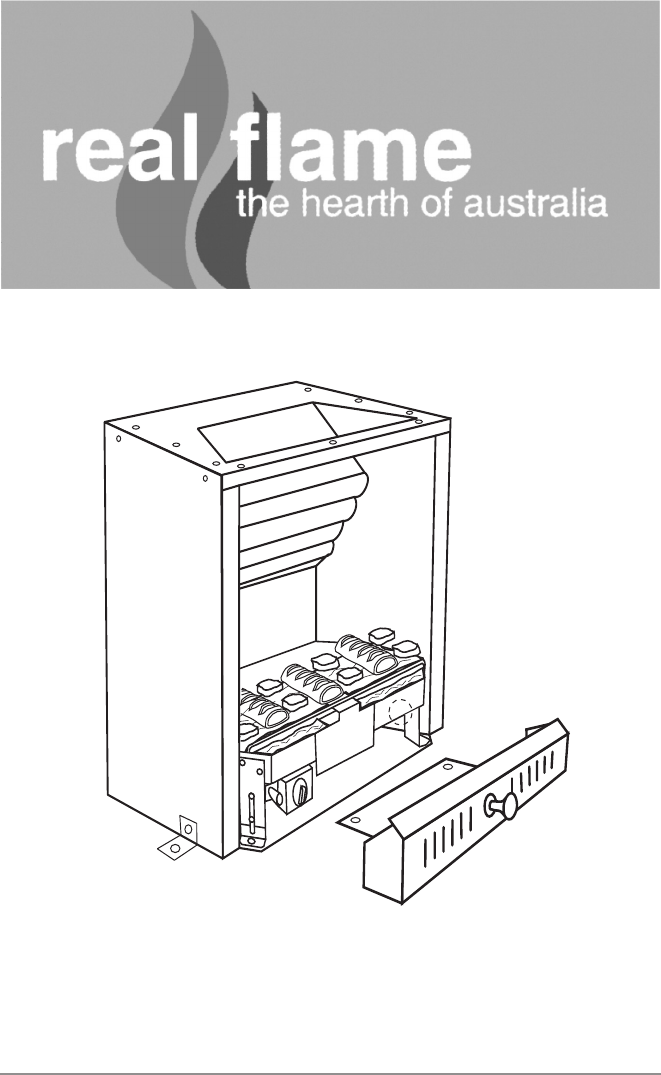
® HOT BOX GAS FIREBOX INSTALLATION & OPERATING MANUAL The Hot Box Gas Firebox is approved to be installed into a masonary fireplace and as a zero clearance firebox and is designed to operate on Natural Gas and Propane (LPG) gases ONLY. Approval Number 6094. Installed primarily as a decorative appliance. Not certified as a Space Heater.
WARRANTY Provided your Real Flame gas fire is installed in strict accordance with our installation instructions, the firebox is unconditionally guaranteed for ten years and all other parts for twelve months from date of purchase. This unconditional warranty covers part and labour at our discretion taking into consideration normal wear and tear and does not cover fires installed in outdoor settings.
CONTENTS Contents ..................................................................................................................3 Data Plate.................................................................................................................4 Installation Instructions ............................................................................................5 Commissioning Procedure ......................................................................................
DATA PLATE (Affixed to burner) 4 NATURAL GAS LPG Injector 2.5 1.3 Mj/Hr 26 23 P.T.P. 0.8 2.
INSTALLATION INSTRUCTIONS INSTALLATION INTO AN EXISTING FIREPLACE The Hot Box system is designed to be installed behind a cast iron insert or fascia. 1. Check that the fireplace and chimney are in working order, sound condition and clean and free from obstructions. Any cracks or gaps found in the masonary of the fireplace, must be sealed prior to the installation of the Hot Box. 2. Measure the fireplace opening to ensure that the Hot Box will fit into the opening. 3.
COMMISSIONING PROCEDURE (continued) WARNING Care must be taken to ensure that any return air register exhaust system does not adversely affect the operation of the appliance or draught of chimney or flue. “DO NOT place articles on or against this appliance.” “DO NOT use or store flammable materials near this appliance.” “DO NOT spray aerosols in the vicinity of this appliance while it is in operation.” CLEARANCES FROM COMBUSTIBLES 25mm 425mm Cast iron fascia 930mm DIAGRAM 1.
INSTALLATION INTO AN EXISTING FIREPLACE HOT BOX CAST IRON FASCIA MANTEL PIECE GAS INLET HOLE 225mm GAS COWL ENSURE THAT EXHAUST PORT IS NOT RESTRICTED IN ANY WAY.
HOT BOX FOR EXISTING FIREPLACE OVERALL DIMENSIONS 230 455 260 135 350 570 GAS ENTRY POINT HEARTH LOCATION LUGS 8
DIMENSIONS A B C 570 455 230 9
FRAMEOUT INTO ROOM SPECIFICATION SHEET 1 D 90mm x 38mm ON EDGE C 25mm FRAMEOUT DIMENSIONS Model Hot Box 10 A 800 B 510 C 425 A B D 1800 25mm
FRAMEOUT INTO ROOM SPECIFICATION SHEET 1 SPECIFICATION SHEET 1.
ZERO CLEARANCE HOT BOX OVERALL DIMENSIONS 170mm 460mm FLUE INNER 150MM OUTER 200MM 305mm 130mm 135mm 570mm GAS ENTRY POINT 230mm 12
ZERO CLEARANCE HOT BOX COMPONENTS OUTER CASING FLUE COLLAR INNER CASING 3.
ZERO CLEARANCE HOT BOX ASSEMBLY Using screws provided: 14 1. Fit inner casing to Hot Box. 2. Fit flue collar to inner casing. 3. Fit outer casing over both flue collar and inner casing.
OPTIONAL POWER FLUE THE INSTALLATION MANUAL OF THE REAL FLAME POWER FLUE SYSTEM IS TO BE READ IN CONJUNCTION WITH THE INSTALLATION MANUAL OF THE REAL FLAME PRODUCT BEING USED. THE DESIGN OF THE REAL FLAME POWER FLUE SYSTEM IS SUBJECT TO COPYRIGHT AND ALL INFRINGEMENTS WILL BE VIGOROUSLY PURSUED. Introduction - the Power Flue System POWER FLUE DESIGN A ‘flue’ using a fan to remove or assist in removing combustion products from an appliance, is known as a ‘power flue’.
OPTIONAL POWER FLUE (continued) Installation Instructions (continued) LOCATION OF FLUE TERMINAL FOR POWER FLUE Listed below are the minimum clearances required for fan-assisted terminations: 1. Below eaves, balconies and other projections..........................................................200mm 2. From the ground, above a balcony or other surface. ...............................................300mm 3. From a return wall or external corner. ......................................................
OPTIONAL POWER FLUE (continued) Installation Instructions (continued) HORIZONTAL FLUE RUN The maximum length of horizontal flue run is to be 13.5 metres with a maximum of four (4) bends; these bends can be 45° or 90°. The horizontal flue run is to have a grade downwards from the motor to the termination. VERTICAL FLUE RUN The minimum vertical flue run is 900mm from the top of the firebox (1500mm from the floor).
OPTIONAL POWER FLUE (continued) Motor Clearance Minimum clearance 250mm Ensure there is adequate ventilation within this cavity to prevent motor overheating.
OPTIONAL POWER FLUE (continued) Frameout T IMPORTANT Motor Motor Motor Capacitor 4 mf Pressure Differential Switch Fan Fan Casing 19
OPTIONAL POWER FLUE (continued) Internal Motor 500mm Top Termination 300mm min. Access Panel Min. Distance Domestic: 220mm Industrial: 320mm 150mm x 200mm flue extension 200mm Motor Termination 150mm x 200mm twin skin flue (if required) 900mm Baffle Heater 25mm Flue Minimum 25mm clearance from outer flue to combustible interior. NOTE: 1. Maximum of 4 elbows, 45° or 90°. 2. Allow 400mm x 400mm access panel for service of motor.
OPTIONAL POWER FLUE (continued) External Motor 25mm clearance 200mm 340mm External Motor 150mm x 200mm flue extension 150mm x 200mm twin skin flue (if required) Miniumum 1290mm 900mm Baffle Heater NOTE: 1. Maximum of 4 elbows, 45° or 90°.
OPTIONAL POWER FLUE (continued) Wiring Diagram TECHRITE POWER FLUE CONTROL MODULE Sparker Heat Sensor LED Indicator Pressure Switch Power Fan Parts List PART No. 1. Dungs BM.740-007 double block solenoid valve 2. Dungs DGAI.73 Module 5.1.3. 3. Electronic Ignition Sparker 4. Electronic Flame Sensor 5. Ecofit 2GTA35 Motor. Complete with ‘sail’ switch. 6. 22 DESCRIPTION 900mm Real Flame Power Flue Muffler.
TROUBLE SHOOTING FOR ELECTRONIC IGNITION AND POWER FLUE SYSTEM. Symptom Possible Cause Fire turned on and nothing happens No Power to Module Fire turned on and motor starts but there is no spark Pressure switch not operating Check pressure switch Fire sparks when turned on but will not ignite A. No Gas Connect Gas. B. Sparker is to far from metal Adjust sparker so it cross lights to metal. C. Pressure switch (Power Flue) is not operating correctly.
TROUBLE SHOOTING FOR ELECTRONIC IGNITION AND POWER FLUE SYSTEM. (continued) The power flue and electronic control box have a red LED light that indicates the possible cause of a problem, the LED light will flash in different sequences for different problems, the most common are:- 24 Long Flash Short Flash 1 0 Normal Running State. 1 1 Flame Failure.
REAL FLAME PTY LTD ABN 76 006 311 155 Head Office/Factory/Showroom 1340 Ferntree Gully Rd. Scoresby Vic 3179 Ph: (03) 8706 2000 Fax: (03) 8706 2001 E-mail: info@realflame.com.au Richmond - VIC Showroom 300 Swan St. Richmond Vic 3121 Ph: (03) 9428 4443 Fax: (03) 9428 4445 Geelong - VIC Showroom 1/2A Gordon Avenue. Geelong West Vic 3218 Ph/Fax: (03) 5229 0844 E-mail: realflamegeelong@hotmail.com.au Sydney - NSW Showroom 654 Pacific Highway.