
Specifications


TC35 / TC37 Hardware Interface Description
TC35_37_HD_02_V03.10 - Released Page 25 of 92 21.12.2001
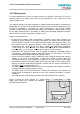
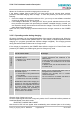
ACCU_TEMP
GND
NTC
Polyfuse
ϑ
Protection Circuit
+
-
Battery cell
BATT+
3.2.2 Battery pack
For some applications the use of a battery pack may be required. TC35 and TC37 can be
powered from a Li-Ion battery pack which must be specified for 3.8V, 0.85Ah and a final
charge voltage of 4.2V.
The charging algorithm has been optimized for a battery pack that meets the characteristics
listed below. It is strongly recommended that the battery pack you want to integrate into your
TC35/TC37 application is compliant with these specifications. This ensures reliable
operation, proper charging and, particularly, allows you to monitor the battery capacity using
the AT^SBC command (see /1/ for details). A battery pack especially designed to operate
with TC35/TC37 modules is specified in Chapter 3.2.2.1.
Battery pack characteristics
• Ensure that the battery pack incorporates a protection circuit. Since charging and
discharging largely depend on the battery temperature, the battery pack should include
an NTC resistor. If the NTC is not inside the battery pack it must be placed nearby. The
NTC resistor must be connected between ACCU_TEMP and GND. Required NTC
characteristics are: 10 kΩ +5% @ 25°C, B
25/50
= 3435K +3% (alternatively acceptable:
10 kΩ +2% @ 25°C, B
25/50
= 3370K +3%). Please note that the NTC is indispensable for
proper charging, i.e. the charging process will not start if no NTC is present.
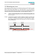
• Furthermore, the protection circuit must be capable of detecting overvoltage (against
overcharging), undervoltage (against deep discharging) and overcurrent. The circuit
must be insensitive to pulse loading (see Chapter 3.2.2.1).
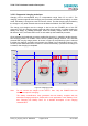
• On the TC35/TC37 module, a built-in measuring circuit constantly monitors the charging
voltage. In the event of undervoltage, it causes the module to power down and
automatically starts up trickle charging to protect the cell from damage. Undervoltage
thresholds are specific to the battery pack and must be evaluated for the intended model.
When you evaluate undervoltage thresholds, consider both the current consumption of
TC35/TC37 and of the application circuit.
• The battery cell must be insensitive to rupture, fire and gasing under extreme conditions
of temperature and charging (voltage, current).
• The battery pack must be protected from reverse pole connection. For example, the
casing should be designed to prevent the user from mounting the battery in reverse
orientation.
• The battery pack must be approved to satisfy the requirements of CE conformity.
Figure 5 shows the circuit diagram of a typical
battery pack design that includes the protection
elements described above.
Figure 5: Battery pack circuit diagram