~ 00@muaJ [?[ill] ~®00000Doorn 0 W00 [f ~ ~(~Jc=~~ [ID I TI~ ffi c=J ITmwooOU®u OO@@@Dw@u TI i7 ~ llYlJ 00 ~ l iJ 00 [f ~ ~~[ID c=J ~TI !2 llYIJ 00 ~ ~00@· 0 TI ·aJ~ PLEASE READ BEFORE USING THIS EQUIPMENT 1-•EALIShC ® CATi. NO.
Your PATROLMAN PR0-16A scanning receiver is a completely transistorized VHF / UHF superheterodyne receiver using dual-conversion for the VHF bands and triple conversion for the UHF band. It is capable of automatically scanning sixteen crystal-controlled channels. Some special features are: four ceramic filters, channel lock-out circui"t, skipper circuit, AFC circuit for UHF band, scan delay circuit (switchable) and AC or DC operation.
PREPARING FOR USE BOTTOM OF CASE To use your PR0-16A, you must do three things: Connect power I nstal I from 1 to 16 crystals Connect an antenna To make a quick check, you can just connect the Line Cord to a source of 120 volts, 60 Hz, AC power. If you intend to use a 12 volt source, you must connect the 12 volt DC power plug wires as noted later on under "Mobile Installation". With an antenna connected and a crystal installed, turn the Receiver on by rotating VOLUME clockwise.
CONTROL LOCATION AND FUNCTION PRIORITY Button-will lock in channel 1 for priority reception over any other active channel. Thus, when pressed in, if a signal comes on this channel, the Receiver will automatically lock-in on it and will stop scanning. When the signal ceases on this channel, the receiver will start scanning once again. OFF-VOLUME is the power switch and Volume control. When not in use, rotate this control to the left to turn it off.
VOLUME/ SCAN RATE SQUELCH Power Control PRIORITY CHANNEL LOCK-OUT BUTTONS (INDICATOR LIGHTS) Control MANUAL SELECTOR SCAN/MANUAL DELAY (01\1-0FF) Button Button Button VHF ANT JACK UHF ANT JACK TAPE OUT JACK AC LINE CORD DC POWER JACK / -5- '
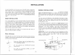
INSTALLATION A good installation will make the most of the PR0-16A's capabilities. Don't loose any of the tiny signals by using an inadequate antenna or poor quality lead in. Use an antenna of correct length and a good quality foam coaxial cable. The antennas that you choose, and how you install them, will have a great effect on how well your receiver will work. Your PR0-16A is designed to utilize two antennas, one for VHF and one for UHF.
t Mobile Antennas MOBILE NOISE SUPPRESSION There are many possible mounting locations on a car. Three of the most popular locations for monitor antennas are shown below. This rece iver is ve ry sens1t1ve, and will pick up signals that are extremely weak. With th is extreme sensitivity, you will fi nd that the receiver wi II amplify weak signals, along with any noise that may be present.
OPERATION After power and antennas are connected and a crystal (or crystals) has been installed, your PR0-16A is ready to use. PRIORITY: Turn VOLUME "on", by rotating to the right. Rotate SQUELCH fully counterclockwise. Set all the Channel Lock-out Buttons "on" (press in). You should hear a rushing sound from the speaker. Now adjust SQUELCH clockwise until you no longer hear the rushing background noise (fu rther explanation of SQUELCH adjustment is noted below).
FREQUENCY COVERAGE Delay circuit is switchable-press DE LAY in to activate the Delay function; leave out to remove this delay. The Priority channel has a separate built-in Delay circuit which is not switchable-so when PRIORITY is activated, you know for sure you won't miss any repli es on that channel.
An interesting service is the Mobile Telephone. FCC has assigned this service channels in· the range of 152.51to152.81 MHz at every 0.030 MHz (channels are 30 kHz apart). Also, 454.375 to 454.95 MHz, with channels 25 kHz apart from 454.375 to 454.625 and then every 50 kHz up to 454.95. As a. general rule on VHF, most activity will be concentrated between 153.785 and 155.98 and then again from 158.73 to 159.46 MHz . Here you'll find local government, police, fire and most such emergency services.
SCHEMATIC DIAGRAM ! I iGND I isv L_ __ ___ ________ _____'. ~AMP . ~G~-- 4425) _ __ _ __ _ _ _ _ _ _ _ __ VHF ANT JACK JI __ _ _ _J TAPE OUT J3 -- ----------r--l®--1J RF I AF ( GE - 198 - 4504) !--~I (1) 1 VR3 501<$) i i UHF ANT JA.CK J2 ~---------__j__!,_I-! ~ci_u~~IAI ! , .
RADIO SHACK LIM ITED WARRANTY This equipment is warranteed against defects for 1 year from date of purchase. Within this period , we will repair it without charge for parts and labor. Simply bring your sa les slip as proof of purchase date to any RadioShack store . Warranty does not cover tra nsportation costs. Nor does it cover equipment subjected to mi suse or accidental dama ge. This Warranty gives you specific legal ri ghts and you may al so have other ri ght s which vary from st ate to stat e.