
User's Manual

RTL8191E-GR
Datasheet
Wireless LAN Network Interface Controller 10 Rev.0.4
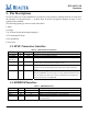
5.3.
Power Pins
Table 3. Power Pins
Symbol Type Pin No Description
LX
P
50 Input VDD33
GND
P
28,41,59 Regulator GND
VD33A
P
3,11,21,39,51 VDD 3.3V for Analog.
VD12D P 36, 58 +1.2V (Digital)
VD18A P 7,15,23 VDD 1.8V for Analog.
VD15A P 24 Analog 1.5V Capacitor
VD33D P 55 VDD3.3V for Digital
VD18D P 37 VDD 1.8V for Digital.
VD12A P 40 VDD 1.2V for Analog
RETX P 22 For Bandgap and Bias
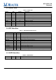
5.4.
RF Interface
Table 4. RTL8191SE-GR RF Interface
Symbol Type Pin No Description
PAPE0 O 1 2.4GHz Transmit Power Amplifier Power Enable.
TRSWP0 O 2 Transmit/Receive Path Select 0.
TX2G_ON0 O 4 RF TX positive signal to antenna A
TX2G_OP0 O 5 RF TX negative signal to antenna A
TRSWN0 O 6 Transmit/Receive Path Select 0.
RX2G_IP0 O 8 RF RX positive signal from antenna A
RX2G_IN0 O 9 RF RX negative signal from antenna A
PAPE1 O 10 2.4GHz Transmit Power Amplifier Power Enable.
RX2G_IP1 I 15 RF RX positive signal from antenna B
RX2G_IN1 I 16 RF RX negative signal from antenna B
ANT_SEL_P O 17 Antenna Control Positive signal
ANT_SEL_N O 18 Antenna Control Negative signal
TSSI_0 I 64 Transmit signal strength indication from external power amplifier
5.5.
LED Interface
Table 4. LED Interface
Symbol Type Pin No Description
LED0, 1 O 19/20 LED Pins (Active low).