rec N-Peak Series INSTALLATION INSTRUCTIONS FOR ALL REC N-PEAK SOLAR PANELS CERTIFIED ACCORDING TO IEC 61215 & IEC 61730
CONTENTS CONTENTS 2 List of figures 2 INTRODUCTION 3 SAFETY MEASURES 4 Safety in the working area 4 Panel handling 4 ELECTRICAL INSTALLATION 5 Electrical requirements 5 MECHANICAL INSTALLATION 5 Fire guidelines 5 Orientation 5 Environmental factors 5 PANEL INSTALLATION 6 Rail specifications 6 Clamp specifications 6 Mounting methods: Clamping with rails parallel to the short side 7 Mounting methods: Clamping with rails parallel to the long side 8 Mounting m
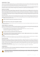
INTRODUCTION Thank you for choosing REC photovoltaic panels for your installation. REC N-Peak solar panels are ideal for delivering long-lasting and reliable power output. They have been created through intelligent design and are manufactured to the highest quality and environmental standards. With correct installation and maintenance, REC panels will provide clean, renewable energy for many years. Please read this entire manual carefully.
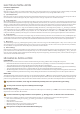
SAFETY MEASURES Installers are responsible for the safe and effective installation and operation of the system and for adhering to all applicable local and national standards and regulations. All relevant local codes and regulations should be referred to and observed as well as regulations on working at heights and fall protection. SAFETY IN THE WORKING AREA i) Safety in the working area Installation of REC solar panels may involve working on rooftops or raised platforms.
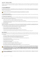
ELECTRICAL INSTALLATION ELECTRICAL REQUIREMENTS i) Application Class REC solar panels are rated for use in electrical Application Class A, Protection Safety Class II; at hazardous levels of voltage (>35V), current(>8A) and power (>240W) where general contact access is anticipated (panels qualified for safety through IEC 61730-1 and -2). ii) System Requirements REC solar panels are only for use where they meet the specific technical requirements of the complete system.
PANEL INSTALLATION REC solar panels are designed for capturing solar radiation and are not suitable for use as overhead or vertical glazing. The IP rating of the junction box provides a level of protection that allows panels to be mounted in any orientation (see product technical specifications for exact rating). Panels must be installed so that the cells are not shaded as this will drastically reduce electrical output.
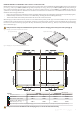
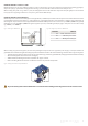
MOUNTING METHODS: CLAMPING WITH RAILS PARALLEL TO THE SHORT SIDE REC N-Peak solar panels secured by clamping to mounting rails has been found to comply with IEC 61215 & IEC 61730 requirements for downward pressure,e.g., snow, of up to 7000 Pa (4666 Pa design load*) and upward pressure,e.g., wind, of up to 2400 Pa (1600 Pa design load*) according to the instructions below (*design loads apply a safety factor of 1.5 to the stated test load, e.g., test load 7000 Pa / 1.5 = 4666 Pa design load).
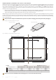
MOUNTING METHODS: CLAMPING WITH RAILS PARALLEL TO THE LONG SIDE REC N-Peak solar panels secured by clamping to mounting rails has been found to comply with IEC 61215 & IEC 61730 requirements for downward pressure,e.g., snow, of up to 5400 Pa (3600 Pa design load*) and upward pressure,e.g., wind, of up to 2400 Pa (1600 Pa design load*) according to the instructions below (*design loads apply a safety factor of 1.5 to the stated test load, e.g., test load 5400 Pa / 1.5 = 3600 Pa design load).
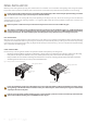
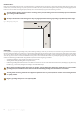
Scale: 1:1.57 MOUNTING METHODS: SLIDE IN SYSTEMS REC N-Peak panels may also be installed using ‘slide-in systems’. Such mounting systems must meet the same specifications including grip lengths, depths and spacing as specified for clamping and the mounting system must be able to withstand the correct load pressures. When installing solar panels using a slide-in system, the drainage holes found in the underside of the panel frame (see fig. 9) must not be covered.
DRAINAGE HOLES Each corner of the REC panel frame has small drainage holes spaced 55 mm from the corner of the panel frame that allow water caused by rain, condensation, snow melt, cleaning or any other process to exit the frame easily and minimize damage caused by freezing and thawing (fig. 9). These holes must not be used for mounting the panel, and they must not be covered by any part of the mounting structure.
CONNECTIONS AND CONNECTORS The connector type(s) used on REC solar panels are indicated in the product specifications at the rear of this manual. The connector IP rating is only valid when they are correctly connected. All connectors and cables must be secure and tight as well as electrically and mechanically sound. UV-resistant cables and connectors approved for outdoor use must be used. Conductor gauge must be chosen to ensure DC power losses (voltage drop) are kept to a minimum (<1%).
MAINTENANCE CLEANING INSTRUCTIONS REC solar panels have been designed for easy maintenance. Cleaning solar panels can however assist in optimizing electricity output. The need for cleaning the panels will vary dependent on location, rainfall, air pollution levels and the angle of installation – the lower the angle of installation, the more cleaning will be required. ‘Normal’ rainfall will naturally clean the panels if installed at a sufficient angle to ensure water runs off the surface.
PANEL CHARACTERISTICS TECHNICAL PROPERTIES: REC N-PEAK SERIES Scale: 1:1.57 Fig. 13: Panel dimensions: REC N-Peak Series GENERAL DATA 1675±2.5 [65.94 ±0.1] 28 [1.1] Cell type: 382.5 [15.05] 910 [35.8] GR 120 half-cut mono c-Si n-type cells 6 strings of 20 cells in series 3.2 mm solar glass with anti-reflection surface treatment Highly resistant polymeric construction Anodized aluminum (black) 3-part, 3 bypass diodes, IP67 rated Glass: GR 1000 [39] Backsheet: 997±2.5 [39.25 ±0.
TECHNICAL PROPERTIES: REC N-PEAK BLACK SERIES Fig. 14: Panel dimensions: REC N-Peak Black Series Scale: 1:1.57 GENERAL DATA 1675±2.5 [65.94 ±0.1] 28 [1.1] Cell type: 382.5 [15.05] 910 [35.8] GR 120 half-cut mono c-Si n-type cells 6 strings of 20 cells in series 3.2 mm solar glass with anti-reflection surface treatment Highly reflective and resistant polymeric construction (black) Anodized aluminum (black) 3-part, 3 bypass diodes, IP67 rated Glass: GR 1000 [39] Backsheet: 997±2.5 [39.25 ±0.
ANNEX 1: INSTALLATIONS ON WATER PLATFORMS This section is applicable to the following products only (other panel types have not yet been qualified for installations on water platforms): • REC N-Peak Series The above named REC solar panels may be installed on water platform-type mounting systems (note that the certification testing of solar panels does not include testing on these types of systems). When installing any of the above named REC solar panels on fixed position (e.g.
ANNEX 2: INSTALLATIONS USING MODULE LEVEL POWER ELECTRONICS This section is applicable to all REC products referred to in this installation manual. Module Level Power Electroncis (MLPE) is the name given to the range of panel-level components that can be installed in PV system circuits installed on or in buildings to reduce shock hazard for emergency responders. MLPE devices can be supplied pre-installed by panel manufacturers or as a ‘retro-fit’ system made by third-party manufacturers.
EC DECLARATION OF CONFORMITY EC Declaration of Conformity Issuer's name and address: REC SOLAR PTE. LTD.
DOCUMENT HISTORY Date Revision Reason 07.2018 A First release 01.2019 B Update to warranty conditions, addition of REC N-Peak Black Series 08.2019 C Updated Datasheets 01.2020 D Updated Datasheets 18 REC Installation Manual - N-Peak - IEC 61215 /61730 Rev D - 01.
REC SOLAR PTE. LTD. 20 TUAS SOUTH AVENUE 14 SINGAPORE 637312 SINGAPORE Tel: +65 6495 9228 Mail: post@recgroup.com www.recgroup.com REC Installation Manual - N-Peak - IEC 61215 /61730 Rev D - 01.