REC SOLAR PANELS INSTALLATION MANUAL Installation instructions for all REC solar panels certified according to IEC 61215 / UL 61730: • REC TwinPeak 4 Series • REC TwinPeak 4 Black Series • REC N-Peak Series • REC N-Peak Black Series • REC N-Peak 2 Series • REC N-Peak 2 Black Series
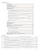
CONTENTS INTRODUCTION 3 SAFETY MEASURES 4 PANEL HANDLING 5 CHOOSING AN INSTALLATION LOCATION 5 ELECTRICAL INSTALLATION 6 MECHANICAL INSTALLATION 6 PANEL INSTALLATION 7 Securing of panels 7 Installation of REC TwinPeak 4 Series panels 8 Mounting REC TwinPeak 4 Series panels with continous rails parallel to short side of the panel 8 Mounting REC TwinPeak 4 Series panels with continous rails parallel to long side of the panel 9 Mounting REC TwinPeak 4 Series panels with short rails 10 Installation of REC N-Pe
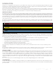
INTRODUCTION Thank you for choosing REC photovoltaic panels for your installation. REC solar panels are ideal for delivering long-lasting and reliable power output. They have been created through intelligent design and are manufactured to the highest quality and environmental standards. With correct installation and maintenance, REC panels will provide decades of clean and renewable energy. Please read this entire manual carefully.
SAFETY MEASURES Installers are responsible for the safe and effective installation and operation of the system and for adhering to all applicable local and national standards and regulations. All relevant local codes and regulations should be referred to and observed. DANGER - Electrical shock Solar panels generate direct current (DC). Once current is flowing, breaking a connection (e.g., disconnecting two panels) can cause an electrical arc.
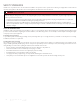
PANEL HANDLING In order to avoid damage, all REC solar panels should be handled with care and protected from damage at all times. All warnings and instructions on the packaging should be observed.
ELECTRICAL INSTALLATION DANGER - Electrical shock Safety is paramount when working on the electrical installation. Always follow the electrical requirements to avoid the risk of sparking, fire hazards, burns and lethal electric shocks.
PANEL INSTALLATION REC solar panels are designed for capturing solar radiation and can be installed where they conform to all local structural regulations. If installing REC solar panels in overhead or vertical constructions, the installer must ensure that all local building codes and regulations specific to such installations are correctly followed. There are different options for securing REC solar panels depending on the design of the array. Mounting hardware is not supplied by REC.
INSTALLATION OF REC TWINPEAK 4 SERIES PANELS MOUNTING REC TWINPEAK 4 SERIES PANELS WITH CONTINOUS RAILS PARALLEL TO SHORT SIDE OF THE PANEL A continous rail (or other support structure) spans the complete underside of the panel. Fig. 3: Clamping of REC TwinPeak 4 Series panels with rails parallel to short side of the panel 0 712 mm [28.0 in] 622 mm [24.5 in] 582 mm [22.9 in] 582 mm [22.9 in] 357 mm [14.1 in] 357 mm [14.1 in] Long Side Mounting 100 mm [3.
MOUNTING REC TWINPEAK 4 SERIES PANELS WITH CONTINOUS RAILS PARALLEL TO LONG SIDE OF THE PANEL A continous rail (or other support structure) spans the complete underside of the panel. Fig. 4: Clamping of REC TwinPeak 4 Series panels with rails parallel to long side of the panel Test Load 1.6 - 2.4 in (40-60 mm) Test Load >2.4 in (>60 mm) Test Load 250 mm [9.8 in] 0 100 mm [3.9 in] 100 mm [3.9 in] 100 mm [3.9 in] Clamping zone 0.8 - 1.6 in (20-40 mm) 250 mm [9.8 in] 0 Clearance Gap 0 650 mm [25.
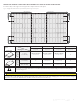
MOUNTING REC TWINPEAK 4 SERIES PANELS WITH SHORT RAILS A short rail (or other short support structure) has a minimum length of 25 mm and does not span the complete underside of a panel. Fig. 5: Clamping of REC TwinPeak 4 Series panels using a short support 0 712 mm [28.0 in] 0 712 mm [28.0 in] 622 mm [24.5 in] 622 mm [24.5 in] 582 mm [22.9 in] 582 mm [22.9 in] 357 mm [14.1 in] 357 mm [14.1 in] M Ma in. 1 x. 2 00 00 mm mm Long Side Mounting 1.6 - 2.4 in (40-60 mm) >2.
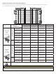
INSTALLATION OF REC N-PEAK PANELS MOUNTING REC N-PEAK PANELS WITH CONTINUOUS RAILS PARALLEL TO SHORT SIDE OF THE PANEL A continuous rail (or other support structure) spans the complete underside of the panel. Fig. 6: Clamping of N-Peak panels on rails parallel to short side of module 25.6 in [650 mm] 0 25.6 in [650 mm] 20.5 in [520 mm] 0 20.5 in [520 mm] 16.5 in [420 mm] 16.5 in [420 mm] 13.4 in [340 mm] 13.4 in [340 mm] 8.2 in [208 mm] 9.
MOUNTING REC N-PEAK PANELS WITH CONTINUOUS RAILS PARALLEL TO LONG SIDE OF THE PANEL A continuous rail (or other support structure) spans the complete underside of the panel. Fig. 7: Clamping of N-Peak panels on rails parallel to long side of module 0 0 25.6 in [650 mm] 9.8 in [250 mm] 4 in [100 mm] 4 in [100 mm] 9.8 in [250 mm] 9.8 in [250 mm] 4 in [100 mm] 9.8 in [250 mm] 0 4 in [100 mm] 0 25.
MOUNTING REC N-PEAK PANELS WITH SHORT RAILS A short rail (or other short support structure) has a minimum length of 25 mm and does not span the complete underside of a panel. Fig. 8: Clamping of REC N-Peak Series panels using short rails 25.6 in [650 mm] 0 25.6 in [650 mm] 20.5 in [520 mm] 0 20.5 in [520 mm] 16.5 in [420 mm] 16.5 in [420 mm] 13.4 in [340 mm] 13.4 in [340 mm] 8.2 in [208 mm] 9.8 in [250 mm] 4 in [100 mm] 0 0 9.8 in [250 mm] 4 in [100 mm] 4 in [100 mm] M Ma in. 1 x.
INSTALLATION OF REC N-PEAK 2 SERIES PANELS MOUNTING REC N-PEAK 2 SERIES PANELS WITH CONTINOUS RAILS PARALLEL TO SHORT SIDE OF THE PANEL A continous rail (or other support structure) spans the complete underside of the panel. Fig. 9: Clamping of REC N-Peak 2 Series panels with rails parallel to short side of the panel 0 712 mm [28.0 in] 622 mm [24.5 in] 582 mm [22.9 in] 582 mm [22.9 in] 357 mm [14.1 in] 357 mm [14.1 in] Long Side Mounting 100 mm [3.
MOUNTING REC N-PEAK 2 SERIES PANELS WITH CONTINOUS RAILS PARALLEL TO LONG SIDE OF THE PANEL A continous rail (or other support structure) spans the complete underside of the panel. Fig. 10: Clamping of REC N-Peak 2 Series panels with rails parallel to long side of the panel Test Load 1.6 - 2.4 in (40-60 mm) Test Load >2.4 in (>60 mm) Test Load 250 mm [9.8 in] 0 100 mm [3.9 in] 100 mm [3.9 in] 100 mm [3.9 in] Clamping zone 0.8 - 1.6 in (20-40 mm) 250 mm [9.8 in] 0 Clearance Gap 0 650 mm [25.
MOUNTING REC N-PEAK 2 SERIES PANELS WITH SHORT RAILS A short rail (or other short support structure) has a minimum length of 25 mm and does not span the complete underside of a panel. Fig. 11: Clamping of REC N-Peak 2 Series panels using a short support 0 712 mm [28.0 in] 0 712 mm [28.0 in] 622 mm [24.5 in] 622 mm [24.5 in] 582 mm [22.9 in] 582 mm [22.9 in] 357 mm [14.1 in] 357 mm [14.1 in] M Ma in. 1 x. 2 00 00 mm mm Long Side Mounting 1.6 - 2.4 in (40-60 mm) >2.
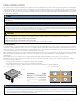
TwinPeak 2S 72 MOUNTING METHODS: Scale 1:1SLIDE IN SYSTEMS When installing using slide in systems the mounting system must meet the same specifications including grip lengths, depths and spacing as specified 04.10.16 for clamping and the mounting system must be able to withstand the correct load pressures. When installing solar panels using a slide-in system, the drainage holes found in the underside of the panel frame (see fig. 16) must not be covered.
DRAINAGE HOLES On the long and short sides of the REC frame small drainage holes can be found that allow humidity and water to exit the frame easily and minimize damage (fig. 16). These are spaced 55 mm from the corner on 60-cell format panels and 60 mm on 72-cell format panels. These holes must not be used for mounting the panel, and they must not be covered by any part of the mounting structure.
CONNECTIONS AND CONNECTORS The connector type(s) used on REC panels are indicated in the product specifications at the rear of this manual. The connector IP rating is only valid when correctly connected. All connectors and cables must be secure and tight as well as electrically and mechanically sound. UV-resistant cables and connectors approved for outdoor use must be used. Conductor gauge must be chosen to ensure DC power losses (voltage drop) are kept to a minimum (<1%).
PANEL MAINTENANCE CLEANING INSTRUCTIONS REC solar panels have been designed for easy maintenance. However cleaning solar panels can assist in optimizing electricity output. The need for cleaning will vary dependent on location, rainfall, pollution levels and the angle of installation – the lower the angle of installation, the more cleaning will be required. ‘Normal’ rainfall will naturally clean the panels if installed at a sufficient angle to ensure water runs off the surface.
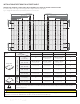
PANEL CHARACTERISTICS REC TWINPEAK 4 SERIES TECHNICAL PROPERTIES: REC TWINPEAK 4 SERIES Fig. 20: Panel dimensions: REC TwinPeak 4 Series GENERAL DATA 1755±2.5 [69.10 ±0.1] 455 [17.91] 845 [33.27] 28 [1.1] GR GR 156 [6.14] 1100 [43.3] Cell type: 120 half-cut mono c-Si p-type cells 6 strings of 20 cells in series Glass: 0.13” (3.
REC TWINPEAK 4 BLACK SERIES TECHNICAL PROPERTIES: REC TWINPEAK 4 BLACK SERIES Fig. 21: Panel dimensions: REC TwinPeak4 Black Series GENERAL DATA 1755±2.5 [69.10 ±0.1] 455 [17.91] 845 [33.27] 28 [1.1] GR GR 156 [6.14] 1100 [43.3] Cell type: 120 half-cut mono c-Si p-type cells 6 strings of 20 cells in series Glass: 0.13” (3.
REC N-PEAK SERIES TECHNICAL PROPERTIES: REC N-PEAK SERIES Fig. 22: Panel dimensions: REC N-Peak Series Scale: 1:1.57 1675±2.5 [65.94 ±0.1] 28 [1.1] GENERAL DATA 382.5 [15.05] 910 [35.8] Cell type: GR Glass: 956 [37.64] 3-part, 3 bypass diodes, IP67 rated in accordance with IEC 62790 Cable: 12 AWG (4 mm²) PV wire, 39 + 47” (1 m + 1.2 m) in accordance with EN 50618 in accordance with IEC 62852 IP68 only when connected Origin: 1200 [47] MECHANICAL DATA GR 30 [1.2] 65.9 x 39.25 x 1.
REC N-PEAK BLACK SERIES TECHNICAL PROPERTIES: REC N-PEAK BLACK SERIES Fig. 23: Panel dimensions: REC N-Peak Black Series Scale: 1:1.57 1675±2.5 [65.94 ±0.1] 28 [1.1] GENERAL DATA 382.5 [15.05] 910 [35.8] Cell type: GR Glass: 956 [37.64] Anodized aluminum Junction box: 3-part, 3 bypass diodes, IP67 rated in accordance with IEC 62790 Cable: 12 AWG (4 mm²) PV wire, 39 + 47” (1 m + 1.
REC N-PEAK 2 SERIES TECHNICAL PROPERTIES: REC N-PEAK 2 SERIES Fig. 24: Panel dimensions: REC N-Peak 2 Series GENERAL DATA 1755±2.5 [69.10 ±0.1] 455 [17.91] 845 [33.27] 28 [1.1] GR GR 156 [6.14] Cell type: 120 half-cut mono c-Si n-type cells 6 strings of 20 cells in series Glass: 0.13” (3.2 mm) solar glass with anti-reflection surface treatment 1100 [43.3] Backsheet: Highly resistant polymeric construction Frame: Anodized aluminum (black) with silver support bars GR 999 [39.33] 6.6±0.2 [0.
REC N-PEAK 2 BLACK SERIES TECHNICAL PROPERTIES: REC N-PEAK 2 BLACK SERIES Fig. 25: Panel dimensions: REC N-Peak 2 Black Series GENERAL DATA 1755±2.5 [69.10 ±0.1] 455 [17.91] 845 [33.27] 28 [1.1] GR GR 156 [6.14] Cell type: 120 half-cut mono c-Si n-type cells 6 strings of 20 cells in series Glass: 0.13” (3.2 mm) solar glass with anti-reflection surface treatment 1100 [43.
ANNEX 1: INSTALLATIONS ON WATER PLATFORMS The REC solar panels covered by this manual may be installed on water platform-type mounting systems (note that the certification testing of solar panels does not include testing on these types of systems). When installing REC solar panels on fixed position (e.g., anchored) water platforms, for example, floating pontoons, follow the instructions below specific to such applications. Failure to do so will invalidate the warranty.
ANNEX 2: INSTALLATIONS USING MODULE LEVEL POWER ELECTRONICS This section is applicable to all REC products referred to in this installation manual. Module Level Power Electronics (MLPE) is the name given to the range of panel-level components that can be installed in PV system circuits installed on or in buildings to reduce shock hazard for emergency responders. MLPE devices can be supplied pre-installed by panel manufacturers or as a ‘retro-fit’ system made by third-party manufacturers.
DOCUMENT HISTORY Date Revision Reason 09.2017 A First release of combined installation manual for all REC 60-cell solar panels 11.2017 B Textual updates 06.2018 C Addition of REC TwinPeak 2 Mono, updates to panel storage instructions, text updates to clamp positions 01.2019 D Update to warranty conditions 08.2019 E Updated Datasheets 01.2020 F Updated Datasheets 06.2020 G Updated Installation Manual Layout, removed REC Peak Energy Series, inclusion of REC N-Peak Series 09.
REC SOLAR PTE. LTD. 20 TUAS SOUTH AVENUE 14 SINGAPORE 637312 SINGAPORE Tel: +65 6495 9228 Mail: post@recgroup.com www.recgroup.