
Datasheet


Characteristics Conditions Min. Typ. Max.
Output Voltage Range All Series 2.5 17V
Output Current R-72xxP/D 0.2 2.0A
R-73xxP/D 0.3 3.0A
R-74xxP/D 0.4 4.0A
Output Current Limit R-72xxP/D 2.5 3.0A
R-73xxP/D 3.75 4.25A
R-74xxP/D 5.0 5.5A
Short Circuit Input Current All Series 50 100mA
Short Circuit Protection Continuous, automatic recovery
Output Voltage Accuracy (At 100% Load) All Series ±1% ±2%
Line Voltage Regulation (Vin = min. to max. at full load) All Series 0.5 1.0%
Load Regulation (10 to 100% full load) All Series 0.5 1.0%
Ripple & Noise All Series 40mVp-p 70mVp-p
Transient Response (see note 1) 50% Load Change – 100µs 200µs
Vout Over / Undershoot 100mV
Remote ON / OFF (see note 2) Open or High (Power ON) 4.5 28V
Low (Power OFF) 0.8V
Max capacitance Load with normal start-up time, no external diodes 200µF
with <1 second start up time + diode protection circuit 6800µF
Switching Frequency 270 300 330kHz
Shutdown current ON / OFF Pin pulled low 100µA
Quiescent Current Vin = min. to max. at 0% load 30mA
Operating Temperature Range -40°C +85°C
Operating Case Temperature +110°C
Storage Temperature Range -40°C +125°C
Case Material Non-Conductive Black Plastic
Potting Material Epoxy (UL94V-0)
Thermal Impedance Natural Convection 25°C/W
Internal Power Dissipation Ta < 60°C 1.4W
Package Weight 9g
Packing Quantity 15 pcs per Tube
MTBF (Nominal Vout, 100% load) Tamb. = +25°C 749 x 10³hours
Tamb. = +85°C 150 x 10³hours
EN General Safety Report: SPCLVD1301028-1 EN60950-1:2006 + A12:2011
R-7xxx
R-7xxxP_D
Series
Specifications (refer to the standard application circuit, Ta: 25°C)
INNOLINE
DC/DC-Converter
Notes:
1. Requires a 100µF electrolytic or tantalum output capacitor for proper operation in all applications (the capacitor to be placed as close as possible to the output pins).
2. ON / OFF pin driven by TTL (logic gate), open-collector bipolar transistor or open-drain MOSFET.
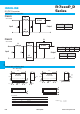
Output Current vs Input Voltage
Ambient Temperature (°C)
90
60
20
40
1.4
10.5
Internal Power Dissipation (W)
0
80
85
How to calculate the max output current
The internal power dissipation(P
D)follows the equation:
P
D = Io × Vo × (1-η)
Io = P
D / Vo × (1-η)
Where P
D = Internal power dissipation
Io = Output current
Vo = Output voltage
η = Efficiency
Example: R-745.0P , at Vin = 28Vdc , Vo = 5Vdc ,η=91% (see "Selection Guide" table)
(a) When Ta = 60°C , P
D = 1.4 Watt (see beside diagram)
Io = 1.4(W) / 5(V) × (1-0.91) = 3.11(A)
(b) When Ta = 85°C , P
D = 1 Watt (see beside diagram)
Io = 1(W) / 5(V) × (1-0.91) = 2.222(A)
(c) At Vin = 12Vdc efficiency = 94% (see "Selection Guide" table)
When Ta = 85°C , P
D = 1 Watt (see beside diagram)
Io = 1(W) / 5(V) × (1-0.94) =3.33(A)
}
Detailed Information see
Application Notes chapter "MTBF"
I-56 www.recom-power.comREV: 2/2016