
Datasheet


RCD-24
LIGHTLINE
DC/DC-Converter
RCD-24
Series
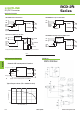
Recommended Class B PCB Layout for Pinned Version
EMI Filter Suggestions
RCD-24-xxx
LED Driver
C1 =
2.2µF
Elect.
Low ESR
-Vin
-LED
+LED
4
5
6
+Vin
L1
1
C2
2
C3
3
C4
C5
C6
C7
C8
C2*
RCD-24-0.30 - RCD-24-0.70
No dimming or PWM dimming:
L1 = 47μH
C2 = C3 = 10nF MLCC
Other caps not required
Analogue Dimming used:
L1 = 120μH
C2 = C7 = 10nF MLCC
Other caps not required
L1
C1
C3
C5
C2
C4
C6
C8
C7
LED-
LED+
Vin+
Vin-
Pin
1
C2*
Top View
Typical Characteristics
CLASS B
RCD-24-1.00 - RCD-24-1.20
L1 = 220μH
C2 = 10nF
C3 = C5 = 2.2nF
C4 = C6 = C7 = C8 = 100nF
All capacitors MLCC
C2* = optional 2μ2 MLCC only if L1
starts to resonate with the back ripple
current.
RCD-24-xxx
LED Driver
C1
-Vin
-LED
+LED
4
5
6
+Vin
L1
1
RCD-24-0.30 - RCD-24-0.70 RCD-24-1.00 - RCD-24-1.20
C1=1μF MLCC C1=2.2μF MLCC
L1 = 22μH L1 = 47μH
CLASS A
Standard Application Circuit (no external components required for normal use)
+Vin
Analogue
Dim
RCD-24-xxx
PWM Dim
On/Off
Snubber circuit optional (needed only for long supply leads or low impedance sources).
Recommended component values = 10µF MLCC + 1R
GND
1st LED
Last LED
(see text)
1
2
3
4
6
5
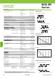
Voltage Across Converter Input Pins
0
20
0
Time (µS)
24.0
40
-20
60 80
-40
Test conditions: 24V supply, 10m long leads.
Without snubber
With snubber
32.4
www.recom-power.com L-5REV: 1/2016
Dropout Voltage/Load
Output Current/Accuracy/Load
Efficiency/Load