
Datasheet

RSO
www.recom-international.com E-127REV: 0/2013
3rd angle
projection
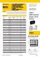
8 PIN SIP Package
XX.X ± 0.5 mm
XX.XX ± 0.25 mm
Pin 8 (NC*) This pin is used internally and must have no external connection. Pin 5 (NC) Not connected internally.
Pin 3 (CTRL)
This pin provides an Off function which puts the converter into a low power mode. When the pin is ‘high’ the converter is OFF and when the pin is high ‘Z’ the converter is ON. There is no
allowed low state for this pin.
ECONOLINE
DC/DC-Converter
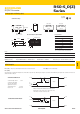
Package Style and Pinning (mm)
12 53678
3.20
0.32
2.0
9.20
21.80
RECOM
RSO-xxxx
****
12 53678
0.50±0.05
4.1
0.50±0.05
11.10
RECOM
RSO-xxxx
****
RECOM
RSO-xxxxD
****
2.54
2.54
1.0
ø
+0.15/0
Top View
Bottom View
Single Output
Dual Output
Recommended Footprint Details
Pin Connections
Pin # Single Dual
1 –Vin –Vin
2 +Vin +Vin
3 CTRL CTRL
5NC NC
6 +Vout +Vout
7 –Vout Com
8 NC* –Vout
NC = No Connection
NC* = NC, but no external Connection allowed.
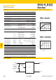
CTRL Examples
-Vin
-Vout
+Vout
+Vin
Ctrl
(TTL)
(see text)
10 KW
20 KW
4.7 KW
RSO/RS
TTL Remote CTRL Circuit
Voltage to be applied via a limiting resistor with a recom-
mended value of 1K for RSO-05xx; 3.3K for RSO-12xx;
4.7K for RSO-24xx and 10K for RSO-48xx.
RSO-S_D(Z)
Series
Control Pin Input Current: 10mA
Control Pin (CTRL) Input
Current, control voltage
applied via 1K resistor,
output voltage must typ. 3mA
reduce to 0V: max. 6mA
-Vin
-Vout
+Vout
+Vin
Remote
(see text)
Optocoupler
RSO/RS
Isolated Remote CTRL Circuit
Notes
Note 1 Maximum capacitive load is defined as the capacitive load that will allow start up in under 1 second without damage to the converter
Certifications
EN General Safety Report: SPCLVD1212007 EN60950-1:2006 + A11:2009+A1:2010+A12:2011
EN Medical Safety Report: MDD1205098-3 + RM1205098-3 IEC/EN 60601-1 3rd Edition Medical Report + ISO14971 Risk Assessment