
Specifications


Electronics and Sensors
87
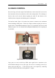
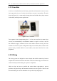
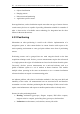
A subsection of the cable system is shown in Figure 4.5 indicating connection of the
motor drivers, battery supply and fuse box. Other cables such as those used for
charging connections and control signals are grouped and attached under the steel
frame to reduce disorder.
Figure 4.5 Subsection of wiring showing motor driver connection
4.2.3 Power Switch Panel
The switch mode ATX power supply, like most modern PC converters do not
completely turn off when the computer is shutdown. They go into what is known as a
"soft" shutdown mode which due to the supply's imperfect efficiency draws a small
quiescent current. To prevent draining of the batteries over time, an external DPDT
toggle switch is used to physically disconnect the power and ground rails from the
supply.
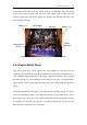
This has been mounted on an easily accessible stainless steel plate, (Figure 4.6), at the
rear of the mechatron chassis. Two additional switches are available for the motor
driver units as it is often necessary to disable the motors while the electronic systems
are running. The switches also provide a convenient "kill-switch" location to shut
down the robot systems in case of emergency.
Batter
y
+ve
Fuse Box
Batter
y
-ve ATX Su
pp
l
y
Motor Driver
Power
Motor
Connector