
Specifications

The Enhancement of a Multi-Terrain Mechatron for Autonomous Outdoor Applications
104
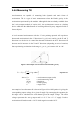
The GPS module was purchased as a standalone OEM unit meaning a suitable power
supply and communication interface was not included. The requirements are a 2.75 –
3.2 V DC supply and as only a 3.3 V rail is available from the ATX converter, a
custom 3 V circuit incorporating an LM317 voltage regulator was constructed. The
serial communication interface uses a 0 – 3V signal at 9600 baud, 8 data bits, no
parity and 1 stop bit. A MAX232 transceiver is used to convert to RS-232 voltage
levels which are fed directly to the serial to USB converter for connection to the PC.
The dimensions of the interface PCB are 60 × 40 mm and include LED's for power
(green) and pulse–per-second (PPS) to indicate the module is operational (red).
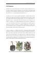
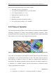
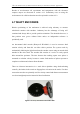
Figure 4.21 LEFT: GPS receiver and interface board in protective case
Mounting of the GPS receiver is by a protective plastic enclosure similar to the
compass module as shown in Figure 4.21. As the GPS receiver does not need to be in
line of sight of the satellites, it is installed inside the metal electronics enclosure
(section 4.10) for safety and aesthetics. Although the antenna will operate within
some types of protective casing, it is positioned at the highest point possible at the
centre of the mechatron. This decreases possible signal degradation and multi-path
effects caused by reflections off other components.
4.6 ACCELEROMETER
The addition of a MMA7260Q inertial sensor from Freescale Semiconductor provides
a means of measuring acceleration of the mechatron. Accelerometers can be used in a
number of applications including robot positioning, impact detection and velocity
detection.