
Specifications


The Enhancement of a Multi-Terrain Mechatron for Autonomous Outdoor Applications
194
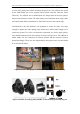
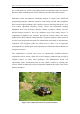
over the guide pulleys and off the mechatron (Figure 6.18). The problem was caused
by the small flange size of the original pulleys which could not retain the tracks
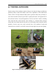
effectively. The solution was to manufacturer new flange disks for the track pulleys
that prevented track movement. The nylon pulleys were machined down using a lathe
and custom made disks of aluminium are fitted with screws to each outside edge.
Consideration to the disk diameter was important to ensure the disks were large
enough to support the tracks during large lateral forces while small enough not to
contact the ground. Two sizes were therefore constructed, one for the upper pulleys
and a smaller diameter for the lower pulleys as shown in Figure 6.19. The addition of
rubber treads was also considered to increase traction and the clearance between
ground and flanges. These were not implemented in this project due to cost but should
be revisited in the future.
Figure 6.18 LEFT: Disengaged track RIGHT: Original pulleys with small flange
Figure 6.19 LEFT: New flange pulleys RIGHT: Track and flange positioning diagram