
Specifications


The Enhancement of a Multi-Terrain Mechatron for Autonomous Outdoor Applications
38
A mechanical commutator is connected to the rotor and winding assembly which
reverses the current polarity as the shaft rotates, thus generating a changing magnetic
field around the windings. The interaction between the changing magnetic dipoles of
the rotor and the constant stator magnets produce a torque and force the rotor to
continuously spin.
3.1.2 Possible Solutions
Two broad categories of motor control are possible, analogue and digital. Analogue
motor controllers, while relatively cheap and easy to implement for small manually
operated drive systems can be very troublesome for computer controlled applications.
A common technique is to convert the digital control signal to an analogue voltage
which then controls the motor voltage with a device such as a variable resistor. This
method is very inefficient and would dissipate excess power as heat, producing
significant stresses on the components. The complexity arises when a mechanical
actuator is required to adjust the variable resistor thus further impeding accurate
motor response.
Digital solutions that utilize relays are a good option when the frequency of switching
is small and no form of velocity control is required. A mechanical relay will only
allow simple on/off operation as a computer controlled mechanical switch. Direction
control can be achieved by adding a second relay for polarity reversal; however the
functionality is still too limited for this project and is not used. The high currents
present in the motors would easily burn out most readily available relays, therefore
expensive industrial grade devices would be required increasing project cost. Relays
also have a limited lifetime due to contact wear so are not suitable for the frequent
operation in a robotic vehicle.
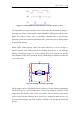
A superior solution is to form a switching arrangement utilizing semiconductor
switches and a digital controller such as an embedded processor. The controller has
the facility to pulse the high power switches with a pulse width modulated (PWM)
square wave, (Figure 3.1) which in turn determines the power delivered to the motors
from the supply by the different levels of duty cycle.