
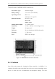
Specifications

Motor Control
65
onboard microcontroller) a resistance between 4.4 kΩ and 5.4 kΩ to be connected
between the throttle +ve and throttle –ve pins.
A 0.5 – 4.5 V signal with respect to the negative battery voltage can be applied to the
throttle wiper pin providing a 2 V range for each direction of motor control. However,
voltage drops between the battery negative point of the driving interface and the
RHINO controller's internal battery negative circuitry will affect the control signal. To
minimize the effect of these common mode voltage drops the ideal solution is for the
driving interface to generate a ± 2 V signal with respect to the average voltage
between throttle +ve and throttle –ve.
When the throttle is in the neutral position the following voltages should be present
with respect to battery negative:
Throttle –ve 0.5 ± 0.1 V
Throttle Wiper 2.5 ± 0.1 V
Throttle +ve 4.5 ± 0.1 V
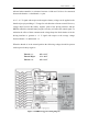
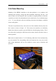
Figure 3.24 RHINO suggested wiring diagram