
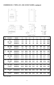
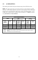
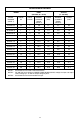
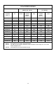
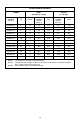
Specifications


16
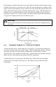
“Variable torque” refers to the fact that the torque required varies with the square of the
speed. Also, the horsepower required varies with the cube of the speed, resulting in a large
reduction in horsepower for even a small reduction in speed. It is easily seen that substantial
energy savings can be achieved by reducing the speed of a fan or pump. For example,
reducing the speed to 50% results in a 50 HP motor having to produce only 12.5% of rated
horsepower, or 6.25 HP. Variable torque drives usually have a low overload capacity (110%
- 120% for 60 seconds), because variable torque applications rarely experience overload
conditions. To optimize efficiency and energy savings, variable torque drives are usually
programmed to follow a variable V/Hz ratio.
The term “constant torque” is not entirely accurate in terms of the actual torque required for
an application. Many constant torque applications have reciprocating loads, such as
vibrating conveyors and punch presses, where the rotational motion of the motor is being
converted to a linear motion. In such cases, the torque required can vary greatly at different
points in the cycle. For constant torque loads, this fluctuation in torque is not a direct
function of speed, as it is with a variable torque load. As a result, constant torque drives
typically have a high overload rating (150% for 60 seconds) in order to handle the higher
peak torque demands. To achieve maximum torque, constant torque drives follow a constant
V/Hz ratio.
Both AC300 & AC400 Series product lines have full overload capacity (150% for 60
seconds, 180% for 30 seconds), so that either one can be used for either type of application.
The V/Hz ratio can also be changed to optimize performance for either type of application.
6.2 DRIVE FUNCTION DESCRIPTION
The AC400 Series is a 16 bit microprocessor based, keypad programmable, variable speed
AC motor drive. There are four major sections: an input diode bridge and filter, a power
board, a control board, and an output intelligent power module.
6.2.1 DRIVE OPERATION
Incoming AC line voltage is converted to a pulsating DC voltage by the input diode bridge.
The DC voltage is supplied to the bus filter capacitors through a charge circuit which limits
inrush current to the capacitors during power-up. The pulsating DC voltage is filtered by the
bus capacitors which reduces the ripple level. The filtered DC voltage enters the inverter
section of the drive, composed of six output intelligent insulated gate bi-polar transistors
(IGBTs) which make up the three output legs of the drive. Each leg has one intelligent IGBT
connected to the positive bus voltage and one connected to the negative bus voltage.
Alternately switching on each leg, the intelligent IGBT produces an alternating voltage on
each of the corresponding motor windings. By switching each output intelligent IGBT at a
very high frequency (known as the carrier frequency) for varying time intervals, the inverter
is able to produce a smooth, three phase, sinusoidal output current wave which optimizes
motor performance.