
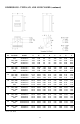
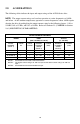
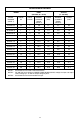
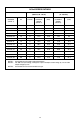
Specifications
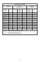


17
6.2.2 CIRCUIT DESCRIPTION
The control section consists of a control board with a 16 bit microprocessor, keypad and
display. Drive programming is accomplished via the keypad or the serial communications
port. During operation the drive can be controlled via the keypad, by control devices wired
to the control terminal strip, or by the the serial communications port. The Power Board
contains the control and protection circuits which govern the six output IGBTs. The Power
Board also contains a charging circuit for the bus filter capacitors, a motor current feedback
circuit, a voltage feedback circuit, and a fault signal circuit. The drive has several built in
protection circuits. These include phase-to-phase and phase-to-ground short circuit
protection, high and low line voltage protection, protection against excessive ambient
temperature, and protection against continuous excessive output current. Activation of any
of these circuits will cause the drive to shut down in a fault condition.
6.2.3 AC400 ANALOG INPUT SIGNALS
The drive allows for three speed reference input signals: speed potentiometer (10,000 Ohm),
4-20 mA, or 0-10 VDC. For control by a speed pot, the wiper lead is connected to terminal
TB-5A, and the high and low end leads are connected to terminals TB-6 and TB-2,
respectively. For 4-20 mA control, wire the positive to terminal TB-5B and the negative to
terminal TB-2. For 0-10 VDC control, wire the positive to terminal TB-5A and the negative
to terminal TB-2. Refer to the diagrams in Section 15.0 - AC400 CONTROL WIRING
DIAGRAMS.
The input impedance of terminal TB-5A (0-10 VDC input) is 200 kilohms, and the input
impedance of terminal TB-5B (4-20 mA input) is 100 ohms. Terminal TB-2 is circuit
common.
6.2.4 AC400 ANALOG OUTPUT SIGNALS
There are two terminals that can supply analog output signals proportional to output
frequency or load. Terminal TB-10A can provide a 0-10 VDC or a 2-10 VDC signal
proportional to output frequency, and TB-10B can provide the same signals proportional to
load. The 2-10 VDC signals can be converted to a 4-20 mA signal using a resistor in series
with the signal such that the total circuit resistance is 500 Ohms. See Parameters: 42 -
TB10A OUT, 43 - @TB10A, 44 - TB10B OUT, and 45 - @TB10B in Section 18.0 -
DESCRIPTION OF PARAMETERS.
NOTE: These analog output signals cannot be used with “loop-powered” devices that
derive power from a 4-20 mA signal.