Wireless 900 MHZ WIRELESS STEREO SPEAKERS INSTALLATION AND OPERATING INSTRUCTIONS AW820
Wireless Stereo Speakers Installation and Operation Manual Model AW820 CONTENTS Connect the Transmitter .............................................................................................. 4 Power the Speakers .................................................................................................... 5 Adjust the Transmitter.................................................................................................. 6 Tune the Headphones .............................................
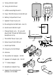
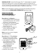
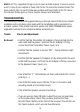
Front A. Tuning Indicator Light Back B. Tuning Control Wheel A C. Left/Monaural/Right Switch D. Power ON-OFF/Volume Control Wheel E. Battery Compartment Cover OFF L TUNING F. Speaker Power Input Jack R MONO POWER/VOLUME B C D E F G. Mounting Bracket Bolt Hole - see (S) G H. Audio Level Indicator Light I. Charge Output Jack – for use with Advent AW770 and AW720 Wireless Headphones only Bottom N J. Transmitter Power Input Jack M H K. Output Level Control Wheel L.
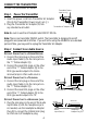
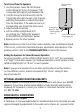
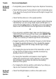
CONNECT THE TRANSMITTER Connect the transmitter as follows: Transmitter Power Input Jack (J) Step 1 Power the Transmitter DC 12V FREQ. ADJUST 1. Insert the power cord from Transmitter AC Adapter (O) into the Transmitter Power Input Jack (J). 2. Plug the Transmitter AC Adapter (O) into Transmitter AC Adapter (O) any standard wall outlet.
WARNING: DO NOT connect the RCA plugs of the “Y” Cable Adapter to a speaker output on the audio source. If you use the speaker output of an audio source to connect the transmitter, you will permanently damage the transmitter. It is designed to work with RCA-type line/variable outputs or headphone outputs only. Note: For more information on hooking up and using the transmitter with various ouputs, please see MORE HELPFUL INFORMATION beginning on Page 7.
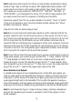
ADJUST THE TRANSMITTER Adjust the transmitter as follows. Step 1 Turn ON your Audio Source (i.e. Stereo Receiver, TV, etc.) so that you can hear sound coming from the source. Step 2 Pivot the Antenna (N) to the upright, vertical position. Step 3 Set the Transmitter “Level” 1. Set the Frequency Control Wheel (M) to its midpoint. 2. Turn the Output Level Control Wheel (K) all the way to the left (your left when looking at the transmitter controls), as shown. 3.
Turn On and Tune the Speakers 1. Use the speaker Power ON-OFF/Volume Control Wheel (D) to turn the speaker “ON.” Tuning Indicator Light (A) will illuminate red. 2. Turn the Tuning Control Wheel (B) until the Tuning Indicator Light changes color to green, indicating the speaker is tuned to the signal from the transmitter. If the audio source is on and operating, you should now hear sound. 3. Adjust volume as desired. 4.
Hint: Fixed-level audio outputs from stereo receivers/amps will typically be designated as Tape, Tape 1, and Tape 2 outputs, DAT (digital audio tape) outputs, VCR audio output connections, and auxiliary audio outputs. Tape, Tape 1, Tape 2 and DAT outputs are usually marked as ‘TAPE OUTPUT,’ ‘TAPE OUT,’ ‘TAPE REC,’ or ‘TAPE RECORD.’ Jacks designated for phono, CD, LD, DVD or tape playback (PB) are inputs and will not work for purposes of installing the transmitter.
Hint: Most TVs, regardless of age or price, have variable outputs. If you are unsure which, if any of your outputs is fixed, refer to the TV instruction manual. Some TVs have outputs that can switch between variable and fixed. Refer to the TV instruction manual. When given a choice, fixed is always recommended. TROUBLESHOOTING The following troubleshooting guide takes you through some of the more common problems and corrections associated with the installation and/or operation of a wireless system.
Trouble Checks and Adjustments No Sound/ Distortion/ Static • If using battery power, batteries may be low. Replace if necessary. • Check that the speaker Tuning Indicator Light is illuminated green. If not, adjust the Tuning Control Wheel until the light changes from red to green. • Check that the antenna is in the upright position. • Check that the Transmitter Audio Level Indicator Light is flickering intermittently.
SPECIFICATIONS & FEATURES Transmitter Omnidirectional Effective Transmitting Range: Up to 300 feet* Adjustable Audio Level Input Variable Frequency Adjustment between 912.5 and 914.5 MHz Line Audio Input with 3.
WARRANTY ONE YEAR LIMITED WARRANTY Recoton Corporation (the Company) warrants to the original retail purchaser of this product that should the product or any part thereof be proven defective in material or workmanship within One Year from the date of original purchase, such defects will be replaced without charge for parts or labor. This warranty does not apply to any incidental or consequential damages.